3 description of switches – Renesas MCU Board for 4513/4514 Group MCUs M34514T-MCU User Manual
Page 16
( 16 / 42 )
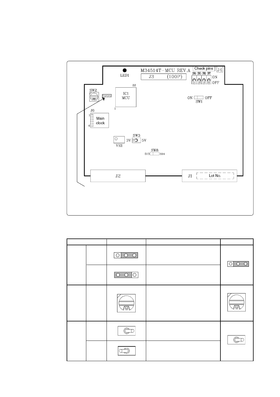
4.3 Description of Switches
The M34514T-MCU board has eight switches. Figure 4.3 shows the positions of these switches.
Tables 4.2 and 4.3 list the functions of the switches and the preset switch positions that are set before
the MCU board is shipped from the factory.
Figure 4.3 Positions of switches
Table 4.2 Functions of switches (1/2)
For the products with the following lot numbers, the position of SW8 is here:
8FS001 - 8FS005, 8GS006 - 8GS020, 8KS021 - 8KS040, 9AS001 - 9AS020,
9CS021 - 9CS060, 9GS061 - 9GS090, 9JS091 - 9JS140
Connects the V
DD
of the M34514T-MCU
to the V
DD
of the target system.
Set the MCU’s ROM size.
• Set "2" (M2)
• Set "4" (M4)
• Set "6" (M6)
• Set "8" (M8)
Operates the target MCU at +5 V.
Operates the target MCU at + 3 V.
8
SW1
SW2
SW3
OFF
ON
5 V
3 V
OFF
5V
Label
Switch position
Description
Factory-setting
ROMSIZE
OFF
OFF
ON
ON
3V
3V
5V
5V
Does not connect the V
DD
of the M34514T-
MCU to the V
DD
of the target system.
- Single-Chip Microcomputer M34551T2-MCU (42 pages)
- M3T-FLX-80NRA (6 pages)
- 70 (162 pages)
- M16C/30P (102 pages)
- PROM Programming Adapter PCA7427G02 (20 pages)
- R0E572110CFK00 (40 pages)
- H8/325 Series (20 pages)
- Single-Chip Microcomputer H8/36079 (27 pages)
- Direct Dummy IC M3T-DIRECT100S (4 pages)
- M3A-2152 (95 pages)
- PCA7755D (6 pages)
- M16C/6N5 (106 pages)
- SH7085 (50 pages)
- QFP-144 (23 pages)
- H8/3834 Series (22 pages)
- RSKM16C62P (3 pages)
- H8/33937 (22 pages)
- Single-Chip Microcomputer H8SX/1622 (5 pages)
- E6000 (29 pages)
- PCA7400 (18 pages)
- PCA4738FF-64 (20 pages)
- SuperH HS7339KCU01HE (43 pages)
- M16C FAMILY (103 pages)
- PCA7412F-100 (20 pages)
- 4513 (210 pages)
- M34551E8FP (16 pages)
- Dummy IC M3T-SSOP36B-450 (4 pages)
- Emulation Pod M30100T3-RPD-E (52 pages)
- Converter Board for M30102 M30102T-PTC (4 pages)
- SH7145 (31 pages)
- HS1653ECN61H (36 pages)
- Converter Board R0E521276CFG00 (4 pages)
- PCA7302E1F-80 (18 pages)
- H8/3814 Series (21 pages)
- H8S/2646 Series (20 pages)
- SuperHTM Family SH7125 Series (40 pages)
- M30262T-PTC (4 pages)
- SH7670 (82 pages)
- H8/3864 Series (20 pages)
- Emulator System M3T-MR100 (306 pages)
- 38K0 (6 pages)
- PLQP0176KB-A (40 pages)
- Direct Dummy IC M3T-DIRECT80S (6 pages)
- PCA4738L-80A (26 pages)
- Converter Board R0E5212BACFG00 (6 pages)