Raypak 1005 User Manual
Page 44
4.
When firing at 100%, the desired heater combus-
tion CO2 is between 8.5 and 9.0% for natural gas
and 9.5 and 10.0% for propane with CO less than
100 ppm. If this combustion cannot be achieved
with the net blower suction within the tolerances
specified in Table W, contact the factory. The ref-
erence amp draw reading may help to indicate if
there is a problem with the system or if blower
adjustment is required.
Manifold Check
1.
Check manifold gas pressure at the gas valve out-
let pressure tap (connection “D” in Fig. 47). This
pressure should read per the values in Table X for
natural and propane gas.
2.
If the pressure reading differs by more than ± 0.2
in. WC, STOP – Call the factory for directions
on what to do next!
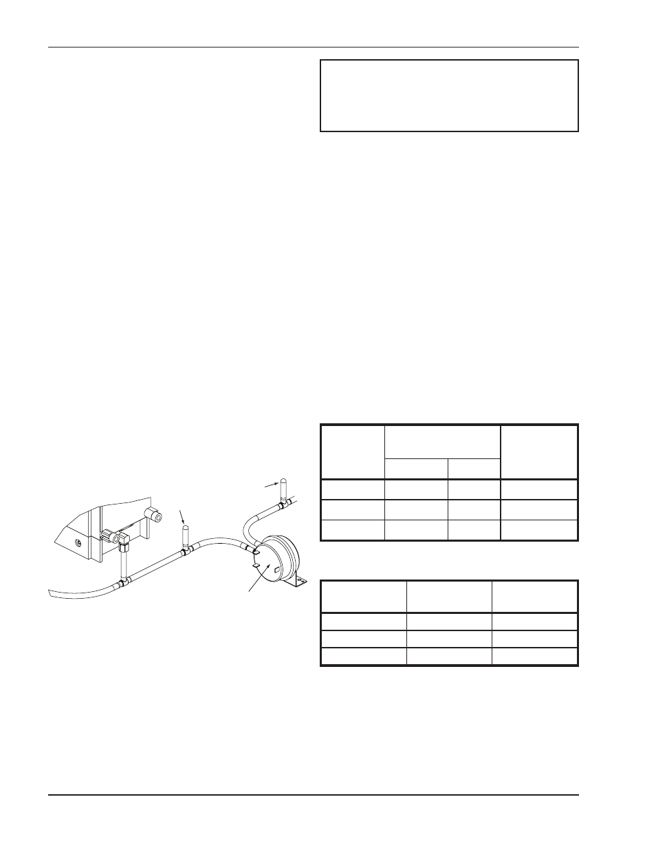
Blower Check
1. Check the net blower suction using a 6-0-6 U-tube
manometer by connecting one end to the blower
suction pressure tee (attached to the negative side
of the air pressure switch, point “A” in Fig. 48) and
the other end to the tracking pressure tee
(attached to the positive side of the air pressure
switch, point “B” in Fig. 48). Read the differential
pressure with the heater firing at 100% input and
compare to Table W.
2. Check the tracking pressure by removing the end
of the U-tube manometer from the blower suction
pressure tee (point “A” in Fig. 48). Replace the
cap on the blower suction tee and check the track-
ing pressure (at point “B” in Fig. 48) with the heater
firing at 100% input. The tracking pressure pro-
vides feedback to the gas regulator to compensate
for various air ducting arrangements and changes
in the pressure drop across the combustion air fil-
ter. Initial readings with a clean air filter installed
must be recorded on the “Start-up Checklist” locat-
ed at the back of this manual. When the tracking
pressure is more negative than -0.6 in. WC for
1005 and 1505 models or -0.8 in. WC on 2005
models and there are no obstructions to the air
intake, replace the combustion air filter. If the air
intake is obstructed, shut the unit off, clear the
obstruction, re-start and check the tracking pres-
sure as previously noted.
3.
FOR REFERENCE ONLY: Measure the blower
amp draw with the heater firing at 100% input and
compare the measured value to the values in
Table X. The amp draw is measured with a clamp-
on type amp probe clamped to the 14 AWG black
power wire going into the blower.
Table W: XTherm Air Pressure Settings
Model No.
Amp Draw
Setting
Tolerance
1005
4.8
+0.0/-0.2
1505
8.1
+0.0/-0.2
2005
13.0
+0.0/-0.5
Table X: XTherm Blower Amp Draw—Reference
Information
44
NOTE: Most commercially available amp probes
are not accurate enough and/or are not shielded well
enough to read accurately in the heater
environment. Blower amp draw readings are for
reference only.
Model No.
Net Blower Suction
(in. WC)
Setting
Tolerance
Nat.
Pro.
1005
-4.8
-2.8
± 0.2 in. WC
1505
-3.5
-3.5
± 0.2 in. WC
2005
-4.6
-5.0
± 0.2 in. WC
AIR PRESSURE SWITCH
A
B
Fig. 48: Air Pressure Measurement Locations