Raypak 1005 User Manual
Page 39
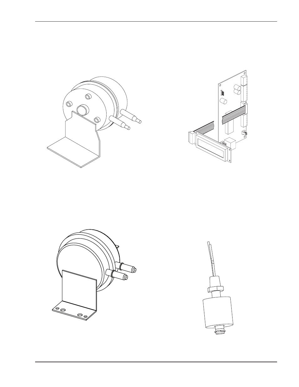
Air Pressure Switch
This heater is equipped with an air pressure switch to
prove the operation of the blower before allowing the
ignition control to begin a trial for ignition. It is located
on the right side of the lower flange of the blower
mounting assembly, directly behind the junction box.
Blocked Vent Switch
This heater is equipped with a blocked vent pressure
switch to prevent the operation of the heater when too
much of the vent is blocked. This switch is located on
the right side of the heater near the right rear corner.
UDB Diagnostic Board
This heater is equipped with a diagnostic board which
will indicate faults as they occur. Refer to the Trouble-
shooting section for instructions on accessing,
reviewing and clearing these faults.
Condensate Float Switch
This heater is equipped with a condensate float switch
to prevent operation when the condensate water level
is too high. The heater shutting down from the conden-
sate float switch is indicative of a blocked drain or
problem with the condensate management system.
The condensate float switch is located inside the vent
outlet plenum at the left rear of the heater.
Fig. 43: Air Pressure Switch
Fig. 44: Blocked Vent Switch
Fig. 45: UDB Diagnostic Board with Display
39
Fig. 46: Condensate Float Switch