Water piping – Raypak 1005 User Manual
Page 14
The heater is supplied with a Section IV “HV” stamped
relief valve sized for the full input of the unit. The relief
valve assembly is shipped loose and must be mount-
ed directly to the heater outlet. No valve shall be
installed between the heater and the relief valve. The
relief valve shall be mounted with its spindle vertical
(see Fig. 1, 2 and 3 on page 6). Relief valve discharge
piping shall provide no less than the cross sectional
area of the relief valve outlet and must be routed to a
safe point of discharge. Installation must comply with
all national, state and local codes.
Temperature & Pressure Gauge
The temperature and pressure gauge is shipped loose
for field installation and must be installed within 12
inches of the boiler outlet (if possible) in an easily
readable location. Installation must comply with ASME
Section IV as well as all applicable national, state and
local codes.
Hydrostatic Test
Unlike many types of heaters, this heater does not re-
quire hydrostatic testing prior to being placed in
operation. The heat exchanger has already been fac-
tory-tested and is rated for 160 psi operating pressure.
However, Raypak does recommend hydrostatic test-
ing of the piping connections to the heater and the rest
of the system prior to operation. This is particularly
true for hydronic systems using expensive glycol-
based anti-freeze. Raypak recommends conducting
the hydrostatic test before connecting gas piping or
electrical supply.
14
3.
For heaters not using a barometric damper in the
vent system, and when air supply is provided by
natural air flow from outdoors for a power burner
and there is no draft regulator, drafthood or similar
flue gas dilution device installed in the same
space, in addition to the opening for ventilation air
required in 1., there shall be a permanent air sup-
ply opening(s) having a total cross-sectional area
of not less than 1 in.
2
for each 30,000 BTUH (74
mm
2
per kW) of total rated input of the burner(s),
and the location of the opening(s) shall not inter-
fere with the intended purpose of the opening(s)
for ventilation air referred to in 1. This opening(s)
can be ducted to a point not more than 18 in. (450
mm) nor less than 6 in. (152 mm) above the floor
level. The duct can also “goose neck” through the
roof. The duct is preferred to be straight down 18
in. (450 mm) from the floor, but not near piping.
4.
Refer to the B149 Installation Code for additional
information.
Water Piping
General
The heater should be located so that any water leaks
will not cause damage to the adjacent area or struc-
tures.
Relief Valve Installation and Piping
WARNING: Care must be taken to ensure that the
equipment room is not under negative pressure
conditions.
WARNING: Pressure relief valve discharge piping
must be piped near the floor and close to a drain to
eliminate the potential of severe burns. Do not pipe
to any area where freezing could occur. Refer to
local codes.
CAUTION: This heater must be installed with a
Primary-Secondary piping arrangement for the
integral pumping system to function properly.
NOTE: Minimum pipe size for the heater inlet/outlet
connections is dependent on the equivalent length of
piping between the load loop and the heater loop,
the operating conditions and the size of the heater.
See Table G on page 16.
WARNING: The pressure relief valve must be
installed at the outlet of the heater. No valve is
permitted to be installed between the heater and the
relief valve.
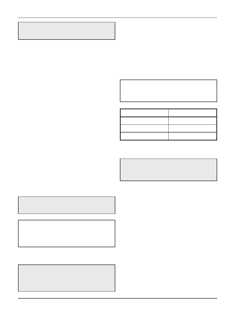
Model No.
Min. Relief Cap.
1005
7 gpm
1505
10.5 gpm
2005
14 gpm
Table F: Minimum UV Relief Valve Capacities
(if required)
NOTE: Some jurisdictions may require that an
additional Section VIII “UV” stamped relief valve be
installed in the heater outlet piping based on local
code requirements.