Gas fireplaces, Warning, Bc d – Regency P33-NG4 User Manual
Page 3: Framing and finishing, Combustible mantels, Mantel leg clearances, Clearance requirements
Framing and Finishing
1) Determine the total thickness of facing material (e.g. drywall plus
ceramic tiles) to allow the fi nished surface to be fl ush with the front
of the unit. Total facing thickness can vary from 1/2” (13mm) to 1-¼”
(32mm) thick.
2) Frame in the enclosure for the unit with framing material.
3) For exterior walls, insulate the enclosure to the same degree as
the rest of the house, apply vapor barrier and drywall, as per local
installation codes. (Do not insulate the fi replace itself.)
4) The top of the unit must not be closer than 30” (762mm) to the
ceiling.
5) Combustible material may be brought up to the top and
sides of the unit and be covered with ceramic tiles, bricks,
rock or other suitable combustible finishing materials.
Note: The unit does not have to be completely enclosed in a
chase. The clearance on top of the unit is 0” to the standoffs
so combustible building materials can be laid directly on top
of the standoffs. You must maintain proper clearances from
the vent to combustible materials (See Below).
6) Use metal studs for framing where the minimum clearance from
the vent to combustible material cannot be maintained.
P33 Gas Fireplace
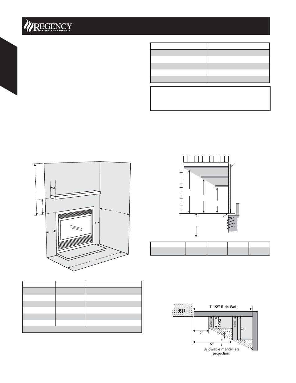
Combustible Mantels
Because of the extreme heat this fi replace emits, the mantel
clearances are critical. Combustible mantel clearances from top of
the louvers are shown in the diagram below. Mantel may be installed
anywhere in the shaded area or higher.
Drywall
Mantel Clearances
2
0
12
6
4
8
10
0
Side View
Top of
Unit
12"(305mm)
3-1/2"(89mm)
7-1/2"(191mm)
A
3”
(76mm)
Standof
f
B
C
D
Note: If desired a non-combustible mantel may be installed at a
lower height.
Note: Ensure the paint that is used on the mantel and the facing
is “heat resistant” or the paint may discolour.
Mantel Leg Clearances
Combustible mantel leg clearances as per diagram below:
Clearances are from the fi nished edge of the unit or an installed front.
Maximum
1-1/2” projection at 2”
minimum clearance.
Mantel Clearances
A
B
C
D
Front
29” (737mm)
11” (279mm)
9” (229mm)
7” (178mm)
WARNING
Failure to maintain required clearances is a major cause of
chimney related fi res. Installation of this fi replace must comply
with these clearances.
Clearance:
Dimension
Measured From:
A: Mantel Height
7” (178mm)
Minimum (Additional on this page)
B: Sidewall
7-1/2” (191mm)
Side of installed front
C: Ceiling
30” (762mm)
Top of installed unit
D: Mantel Depth
12” (305mm)
Maximum (Additional on this page)
E: Alcove Width
48” (1219mm)
Sidewall to Sidewall (Minimum)
F: Alcove Depth
36” (914mm)
Front to back wall (Maximum)
Top of Hearth must not be higher than the base of the fi rebox.
Vent Clearances
Clearance Dimension
Horizontal - Top
2-1/2” (64mm)
Horizontal - Side
1-1/2” (38mm)
Horizontal - Bottom
1-1/2” (38mm)
Vertical - Flex
1-1/2” (38mm)
Vertical - Rigid
1-1/4” (32mm)
E
B
B
A
C
D
F
Clearance Requirements
30
August 2008 Product Specifi cations Book
Gas Fir
eplaces
Gas Fireplaces