Installation, Louver installation, Flueing introduction – Regency Freestanding Gas Stove F39-LPG User Manual
Page 7: Installation precautions, Combustion and ventilation air, Safety precautions for the installer
Regency
®
F39 Room Sealed Freestanding Gas Stove
7
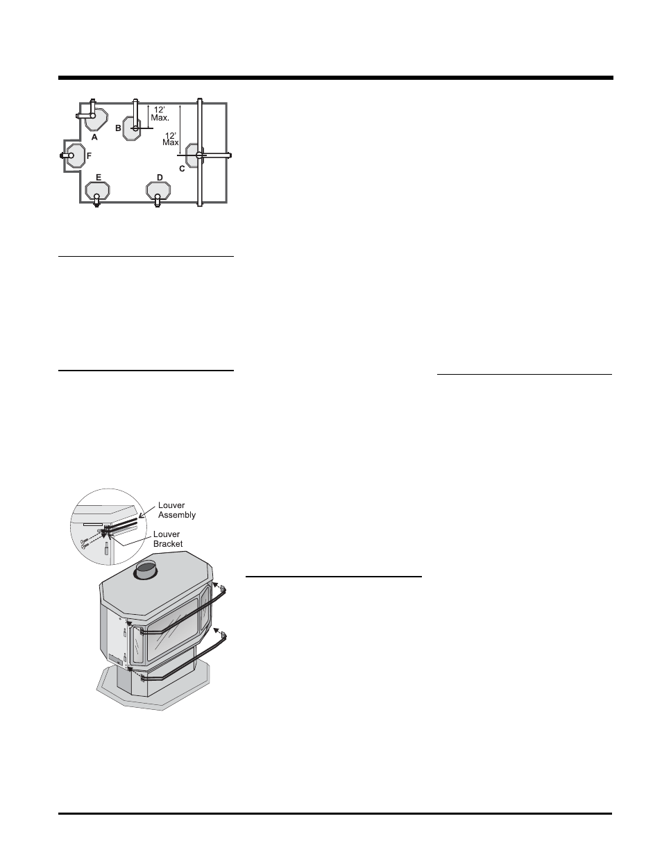
LOUVER
INSTALLATION
1) Attach the top & bottom louvres to the
side stove panel using 2 screws per
side.
INSTALLATION
FLUEING
INTRODUCTION
The DV Stove Horizontal Flue Kit and the
Simpson Dura-Flue Room Sealed System
Model DV-GS fl ueing systems, in combination
with the Regency
®
Room Sealed Freestanding
Gas Stove, F39-NG, and F39-LPG, have been
tested and listed as direct fl ue heater systems
by AGA.
These units use the "balanced fl ue" technology
Co-Axial system. The inner liner fl ues products
of combustion to the outside while the outer pipe
draws outside combustion air into the combus-
tion chamber thereby eliminating the need to
use heated room air for combustion and losing
warm room air up the chimney.
Note: These fl ue pipes must not be con-
nected to any other appliance.
The gas appliance and fl ue system must be
fl ueed directly to the outside of the building,
and never be attached to a chimney serving a
separate solid fuel or gas burning appliance.
Each direct fl ue gas appliance must use it's own
separate fl ue system. Common fl ue systems
are prohibited.
IMPORTANT
Read all instructions carefully before starting the
installation. Failure to follow these instructions
may create a fi re or other safety hazard, and will
void the warranty. Be sure to check the fl uing
and clearance to combustible requirements.
Consult your local building codes before begin-
ning installation.
The location of the termination cap must con-
form to the requirements in the Exterior Flue
Terminal Locations diagram, refer to "Exterior
Flue Termination Location" section.
INSTALLATION
PRECAUTIONS
These fl uing systems are engineered products
that have been designed and tested for use
with the F39-NG, and F39-LPG. The warranty
will be voided and serious fi re, health or other
safety hazards may result from any of the fol-
lowing actions:
1) Installation of any damaged Room Sealed
component
2) Unauthorized modifi cation of the Room
Sealed System
3) Installation of any component part not manu-
factured or approved by Simpson Dura-Flue
or Fireplace Products International Ltd.
For fl ue termination requirements, refer to "Ex-
terior Flue Termination Location" section.
COMBUSTION AND
VENTILATION AIR
The combustion air from this appliance is drawn
from outside the building through the outer fl ue.
Extra provision for combustion air inside the
room is not required.
4) Installation other than as instructed by
Simpson Dura-Flue and Fireplace Products
International Ltd.
Warning: Always maintain required
clearances (air spaces) to nearby
combustibles to prevent a fire
hazard. Do not fi ll air spaces with
insulation.
Be sure to check the fl ue termination clearance
requirements from decks, windows, soffi ts,
gas regulators, air supply inlets and public
walkways as specifi ed in the Exterior Flue
Terminal Locations on page 8 and in your local
building codes.
The gas appliance and fl ue system must be
fl ueed directly to the outside of the building,
and never be attached to a chimney serving
a separate solid fuel or gas-burning appli-
ance. Each direct fl ue gas appliance must use
it's own separate fl ue system. Common fl ue
systems are prohibited.
SAFETY PRECAUTIONS
FOR THE INSTALLER
1) Wear gloves and safety glasses for
protection.
2)
Exercise extreme caution when using
ladders or on roof tops.
3)
Be aware of electrical wiring locations
in walls and ceilings.