Alignment (continued) – RIDGID Table Saw User Manual
Page 32
32
Alignment (continued)
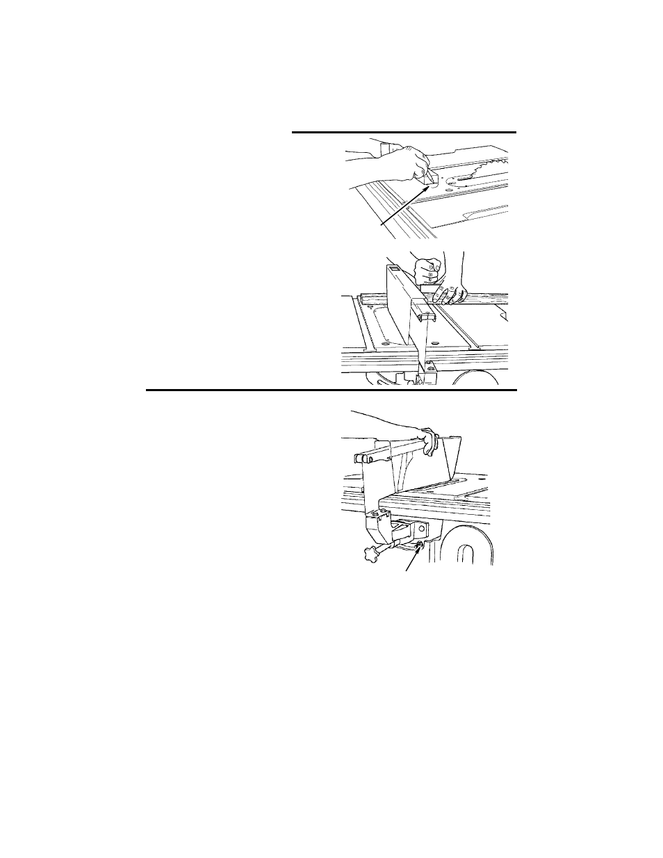
Marking the Ind-I-Cut:
a. With blade 90° (square to table) and
miter gauge in left groove, cross cut
a piece of wood holding the wood
firmly against miter gauge.
b. Pull miter gauge back until freshly cut
edge of wood is over disk. Using a
sharp pencil, mark a line on disk at
freshly cut edge of wood.
c. With miter gauge in right hand
groove, follow same procedure and
mark another line on disk.
d. These lines indicate the “path” of the
cut (kerf) made by the sawblade.
e. When cutting the workpiece, line up
mark on workpiece with line on disk.
NOTE: When the blade is changed, or a
dado/molding head installed these lines
can be erased and reset.
Adjusting Bevel Lock
1. Release blade tilt lock lever and bevel
blade to 45°.
2. Lock blade tilt lock lever, push in to dis-
engage the outer hub of the elevation/
bevel handwheel and with moderate
force attempt to move handwheel
toward the 0° bevel.
3. If blade tilt mechanism cannot be
moved, no additional adjustment is nec-
essary.
4. If blade tilt mechanism can be moved
adjust the blade tilt lock nut by rotating
clockwise 1/4 turn.
5. Repeat steps 3 and 4 as necessary.
6. Release hub of the elevation/bevel
handwheel and move blade tilt mecha-
nism back to 0°.
Marking
Using
Ind-I-Cut
Ind-I-Cut
Blade Tilt
Lock Nut