Crystal choice, Removable component information, Spi eeprom – Renesas EDK3687 User Manual
Page 7
4.2.2. C
RYSTAL
C
HOICE
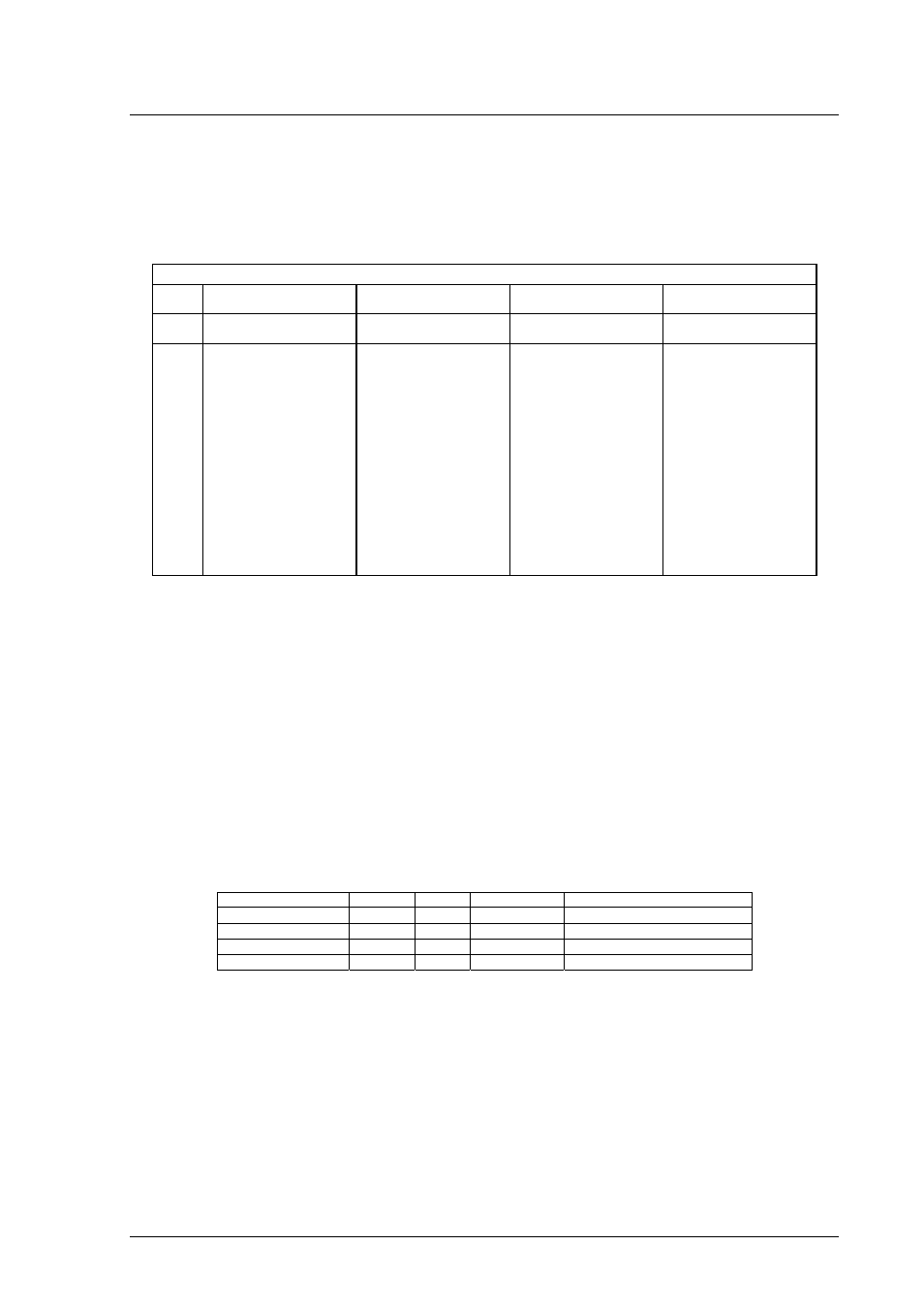
The operating crystal frequency has been chosen to support the fastest operation with the fastest serial operating speeds.
The value of the crystal is 18.432MHz.
The following table shows the baud rates and Baud Rate Register (BRR) setting required for each communication rate using
the above default operating speed. It also confirms the resultant baud rate and the bit error rate that can be expected.
Baud Rate Register Settings for Serial Communication Rates
SMR
Setting:
0 1 2 3
Comm.
Baud
BRR
setting
Actual
Rate
ERR
(%)
BRR
setting
Actual
Rate
ERR
(%)
BRR
setting
Actual
Rate
ERR
(%)
BRR
setting
Actual
Rate
ERR
(%)
110
Invalid Invalid Invalid Invalid Invalid Invalid Invalid Invalid Invalid 81
110
-0.22
300
Invalid Invalid Invalid Invalid Invalid Invalid 119
300
0.00 29
300
0.00
1200 Invalid
Invalid
Invalid
119 1200 0.00 29 1200 0.00 7
1125 -6.25
2400 239 2400 0.00 59 2400 0.00 14 2400 0.00 3
2250 -6.25
4800 119 4800 0.00 29 4800 0.00 7
4500 -6.25 1
4500 -6.25
9600 59 9600 0.00 14 9600 0.00 3
9000 -6.25 Invalid
Invalid
Invalid
19200 29 19200
0.00
7 18000
-6.25
1 18000
-6.25
Invalid
Invalid
Invalid
38400 14
38400 0.00 3
36000 -6.25 Invalid Invalid Invalid Invalid Invalid Invalid
57600 9
57600 0.00 2
48000 -16.67 Invalid Invalid Invalid Invalid Invalid Invalid
115200 4
115200 0.00 0
144000 25.00 Invalid Invalid Invalid Invalid Invalid Invalid
230400* 2
192000 -16.67 Invalid Invalid Invalid Invalid Invalid Invalid Invalid Invalid Invalid
460800* 0
576000 25.00 Invalid Invalid Invalid Invalid Invalid Invalid Invalid Invalid Invalid
T
ABLE
4-2
C
RYSTAL
F
REQUENCIES FOR
RS232
COMMUNICATION
* Note: The device used to convert the RS232 serial information to logic signals for the microcontroller is limited to
120kBaud. The rates above this level can only be utilised if the user provides direct logic level communications.
The user may replace the HC49/U surface mounted AT cut crystal with another of similar type within the operating frequency
of the microcontroller device. Please refer to the hardware manual for the microcontroller for the valid operating range.
Alternatively the user may fit an oscillator module – or provide an external clock source. When providing an oscillator module
or external source it is highly recommended that the load capacitors for the AT crystal are removed from the PCB. These are
physically placed within the PCB outline of the oscillator module for easy location and to ensure they are removed when
using this option.
When changing the crystal frequency the pre-loaded debugging monitor will not function. In this situation the user is
responsible for providing code to evaluate the device away from the default operating speed.
4.2.3. R
EMOVABLE COMPONENT INFORMATION
.
This information is provided to allow the replacement of components removed from the board as described in section 4.2.2.
Component Cct.
Ref
Value Rating
Manufacturer
Load Resistor (X2)
R8
1M
Ω
0805 1%
Welwyn WCR Series
Load Resistor (X3)
R7
1M
Ω
0805 1%
Welwyn WCR Series
Load capacitors (X2)
C2,C3
12pF
0603 10% 25V
AVX 0603 3 A 150 KAT
Load capacitors (X3)
C4,C5
15pF
0603 10% 25V
AVX 0603 3 A 150 KAT
T
ABLE
4-3: R
EMOVABLE
C
OMPONENT
I
NFORMATION
Care must be taken not to damage the tracking around these components. Only use soldering equipment designed for
surface mount assembly and rework.
4.3. SPI
EEPROM
The board has been tested with an Atmel AT25040N-10SA-2.7 SPI EEPROM device (Not supplied).
The device should be connected to P30, P31, P32 and P67 using 0R links on R15, R16, R17 and R21. Alternative
connections are available, refer to section 5.3 for more information.
Do not fit the CAN transceiver if the SPI device is fitted while using the settings above.
7