Edk operation, User interface, Serial interface – Renesas EDK3687 User Manual
Page 6: Connector pin definitions, Edk o, Peration
4. EDK
O
PERATION
4.1. USER
INTERFACE
The EDK provides two buttons for influencing the operation of the board. The purpose of each button is clearly marked next
to it. Refer to the board layout for positions (Section 3)
1. Reset
Switch
This button provides the microcontroller with a reset pulse utilizing the built in power on reset control of the device.
2. NMI
Switch
This button provides a de-bounced signal to the microcontroller for each operation of the button. There is no maximum
activation time for this button.
4.2. S
ERIAL
I
NTERFACE
The serial port on the microcontroller directly supports three wire serial interfaces. Options are provided on the board for the
user to write handshaking routines using standard port pins.
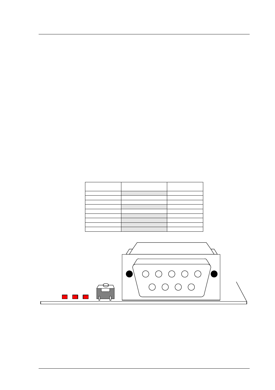
4.2.1. C
ONNECTOR PIN DEFINITIONS
The EDK RS232 interface conforms to Data Communication Equipment (DCE) format allowing the use of 1-1 cables when
connected to Data Terminal Equipment (DTE) such as an IBM PC. The cable used to connect to the EDK will affect the
available board options. A fully wired cable can allow handshaking between the microcontroller and the host PC, subject to
setting the board options and the availability of suitable host software. Handshaking is not supported as standard on the
microcontroller so for normal use a minimal three-wire cable can be used. The minimum connections are unshaded in the
following table.
EDK DB9
Connector Pin
Signal Host
DB9
Connector Pin
1
No Connection
1
2
EDK Tx Host Rx
2
3
EDK Rx Host Tx
3
4
No Connection
4
5 Ground 5
6
No Connection
6
7
EDK CTS Host RTS
7
8
EDK RTS Host CTS
8
9
No Connection
9
T
ABLE
4-1: RS232 I
NTERFACE
C
ONNECTIONS
1
2
3
4
5
6
7
8
9
F
IGURE
4-1: EDK S
ERIAL
P
ORT
P
IN
N
UMBERING
6