Roberts Gorden Caribe CGTH-50 User Manual
Page 34
CGTH I
NSTALLATION
, O
PERATION
AND
S
ERVICE
M
ANUAL
28
4. Install the vent adapter (P/N 90506012) and secure
with #8 x 3/8” sheet metal screws as shown
in Figure 26.
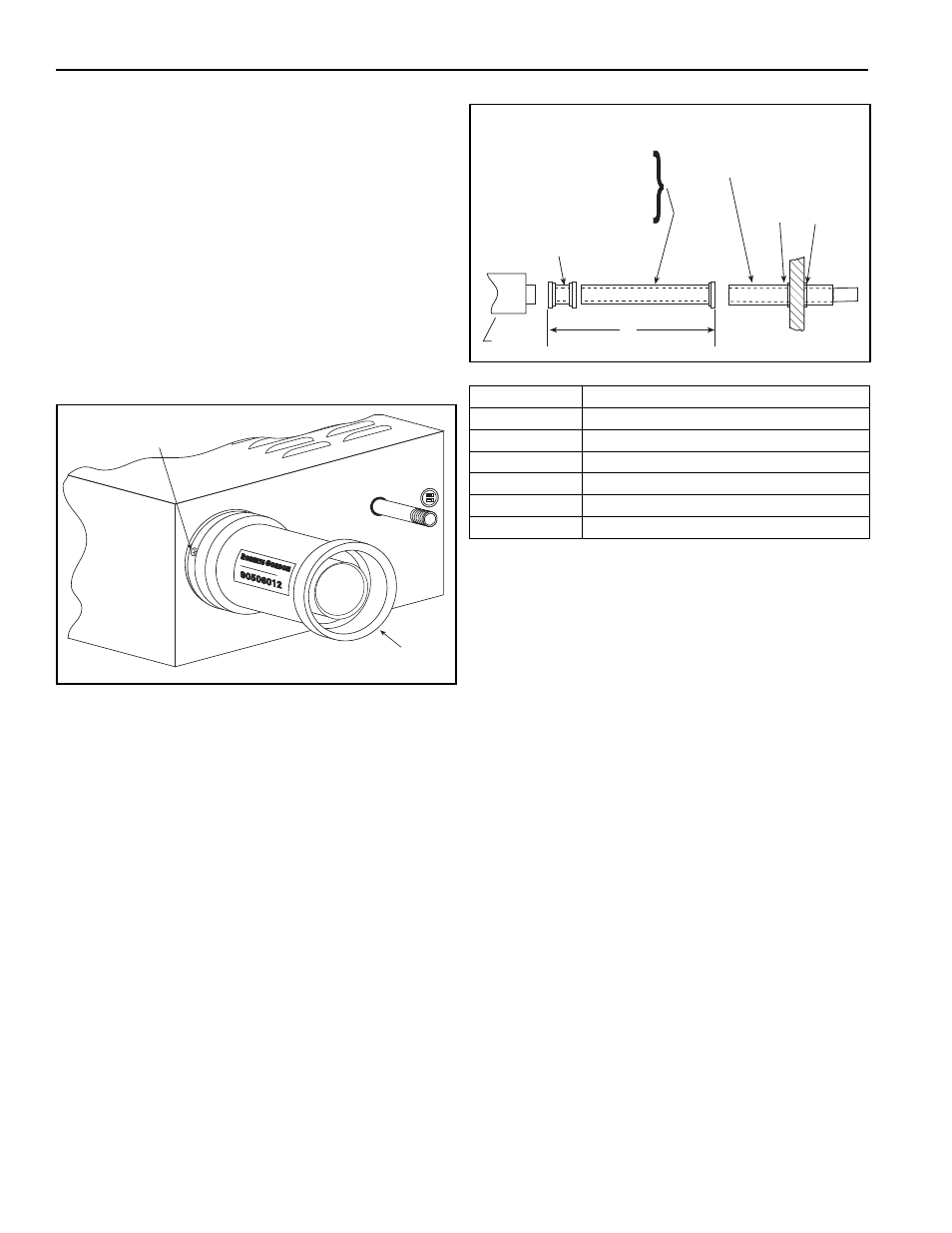
5. If the concentric vent has to be cut (see note on
Page 28), follow instructions A-E (see Figure 27).
If the concentric vent does not have to be cut, see
note on Page 28. Follow instructions A & F below
(See Figure 27).
A. Install the horizontal vent terminal (P/N
90506011) ensure that the air holes intake
hole are facing down. Install the flashing
plates with the hardware supplied.
(See Figure 27.)
FIGURE 26: Flue Collar and Adapter
B. Measure from the end of the adapter to the
end of the vent terminal, dimension C, Page
27, Figure 25. Note the dimension here,
__________.
C. Separate the 3” (80 mm) and the 5” (125
mm) vent by pulling the 3” (80 mm) vent out
from the end with the internal silicone gas-
ket. Remove the internal spring from the
non-silicone gasket end of the 5” (125 mm)
vent.
D. Add 3.5” (90 mm) to the dimension noted in
step B, this is to allow for the internal joint of
the vent. Cut both the 3” (80 mm) and 5”
(125 mm) vent to this length and de-burr the
ends. Always cut from the non-silicone gas-
ket end.
E. Re-assemble the 3” (80 mm) and 5” (125
mm) vent with the internal spacer at the sili-
cone gasket end only.
FIGURE 27: Horizontal Venting Configurations
Table 1: Components
F. Push vent terminal away from heater. Insert
the cut vent in between the adapter and the
vent terminal. Starting at the adapter end,
push the plain end of the vent into the sili-
cone gaskets. The connection will fit firmly
together. If undue force is required to assem-
ble the parts, first check the cut length for
burrs, second apply warm soapy water to the
silicone gaskets.
Note: The gasket construction of this venting is
designed to make a permanent airtight con-
nection, additional silicone sealant and
securing screws are not to be used.
Adapter
P/N 90506012
(3X) Screw
P/N 94118106
Part Number
Description
90506003
Concentric Flue 10” (254 mm)
90506004
Concentric Flue 20” (500 mm)
90506005
Concentric Flue 39” (1000 mm)
90506011
Storm Collar 27.5” (690 mm)
90506012
Burner/Vent Adapter
90506013
Wall Plate
90506013
90506011
90506003
90506004
90506005
90506012
Heater
A
HORIZONTAL