Warning – Roberts Gorden Caribe CGTH-50 User Manual
Page 33
SECTION 5: V
ENTING
I
NSTALLATION
27
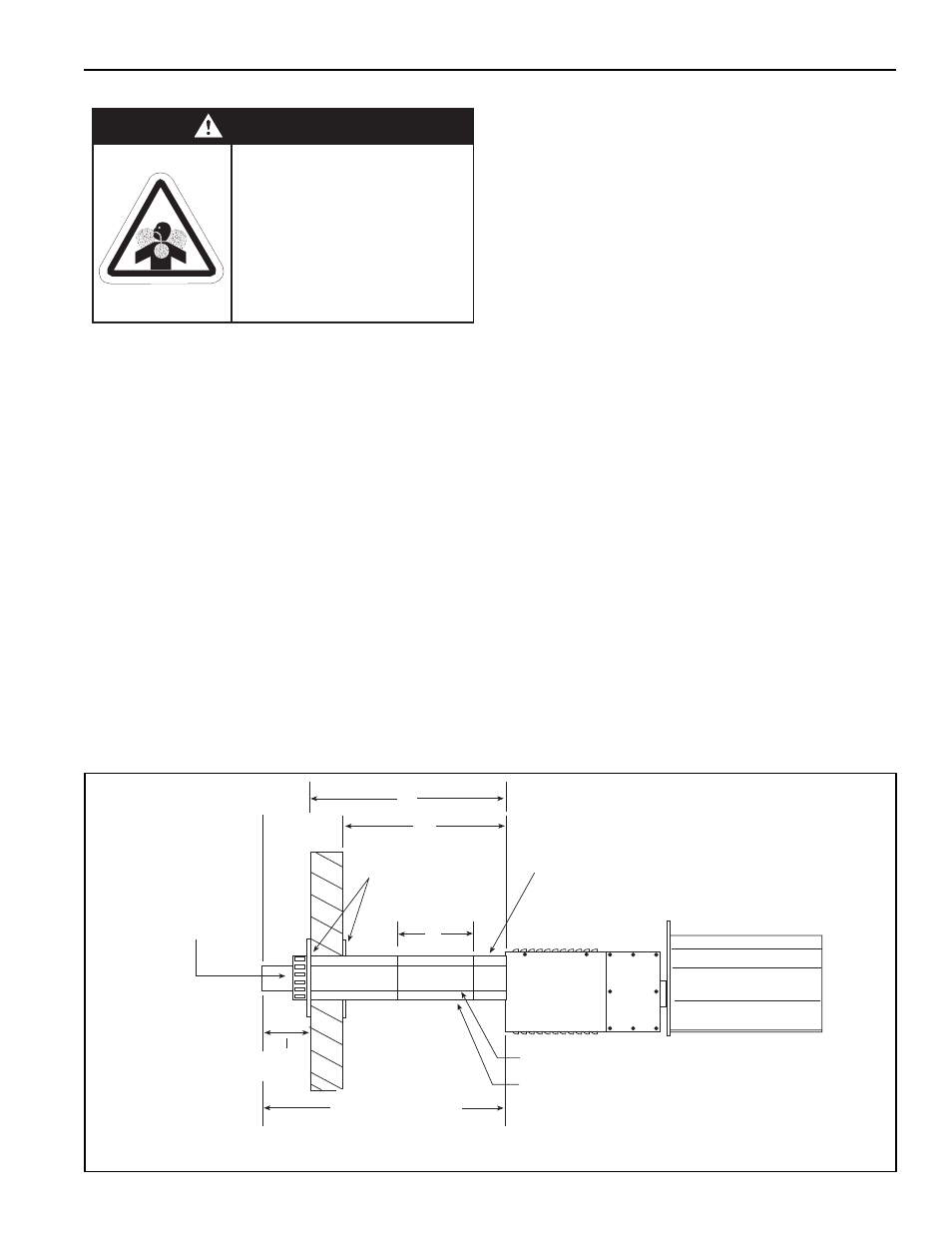
5.4 Cox Geelen Horizontal Venting
After the heater has been properly suspended in
accordance with the preceding headings of this sec-
tion, proceed to install the venting as described
below:
1. Using a tape measure, measure the distance from
the floor to the center of the vent collar on the rear
surface of the burner. Note this dimension here
__________.
2. Using the tape measure, transfer this measure-
ment to the inside surface of the exterior wall that
the vent will penetrate; make a reference mark.
Check the location of the hole to ensure that there
are no internal wall structures (i.e. stud) to prevent
penetration. Also check that the outlet of the vent
does not compromise the general venting require-
ments, See Section 5.1. Cut 5” (125 mm) vent ter-
minal clearance hole as required.
3. Using the tape measure, measure the distance
between the rear surface of the heater and the
exterior wall. Note this dimension here
_________.
A. The following combinations will result in
dimension B from Figure 25:
Horizontal Wall Vent Kit (P/N 08032200) = 25"
(690 mm)
Horizontal Wall Vent Kit (P/N 08032200) +
Concentric Flue 10” (P/N 90506003) = 35"
(889 mm)
Horizontal Wall Vent Kit (P/N 08032200) +
Concentric Flue 20” (P/N 90506004) = 45"
(1143 mm)
Horizontal Wall Vent Kit (P/N 08032200) +
Concentric Flue 39” (P/N 90506005) = 64"
(1626 mm)
Select the appropriate combination for the
distance required. If a shorter distance is
required, see Page 28, Step 5 for cutting
instructions.
FIGURE 25: Horizontal Installation Side View Cox Geelen Venting
Carbon Monoxide Hazard
Heater must be exhausted outside.
Use materials supplied.
This heater needs fresh air for safe
operation and must be installed so
there are provisions for adequate
combustion and ventilation air.
Failure to follow these instructions
can result in death or injury.
WARNING
3" (80 mm) Flue Pipe
P/N 90506011
Wall Terminal
Flashing Plates
5" (125 mm) Air Supply Pipe
P/N 90506012
Concentric Vent
Adapter
A
Heater
Side View
6" (152 mm)
min.
C
B
2' 6"
(762 mm) Minimum
Slope venting down 1/4" (6 mm) per foot towards wall.