Figure 4. installed network module, Network connection – National Instruments FIELDPOINT FP-1600 User Manual
Page 4
FP-1600
4
www.natinst.com
b. Lock the panel mount accessory into place by pushing
the rail clip to the locked position.
c.
Mount the FP-1600 and panel mount accessory onto
the desired surface. You can drill pilot holes using the
directions in the FieldPoint Network Module Panel
Mount Accessory installation guide.
3. Add terminal bases with their local bus connectors firmly
mated to the FP-1600 local bus connector.
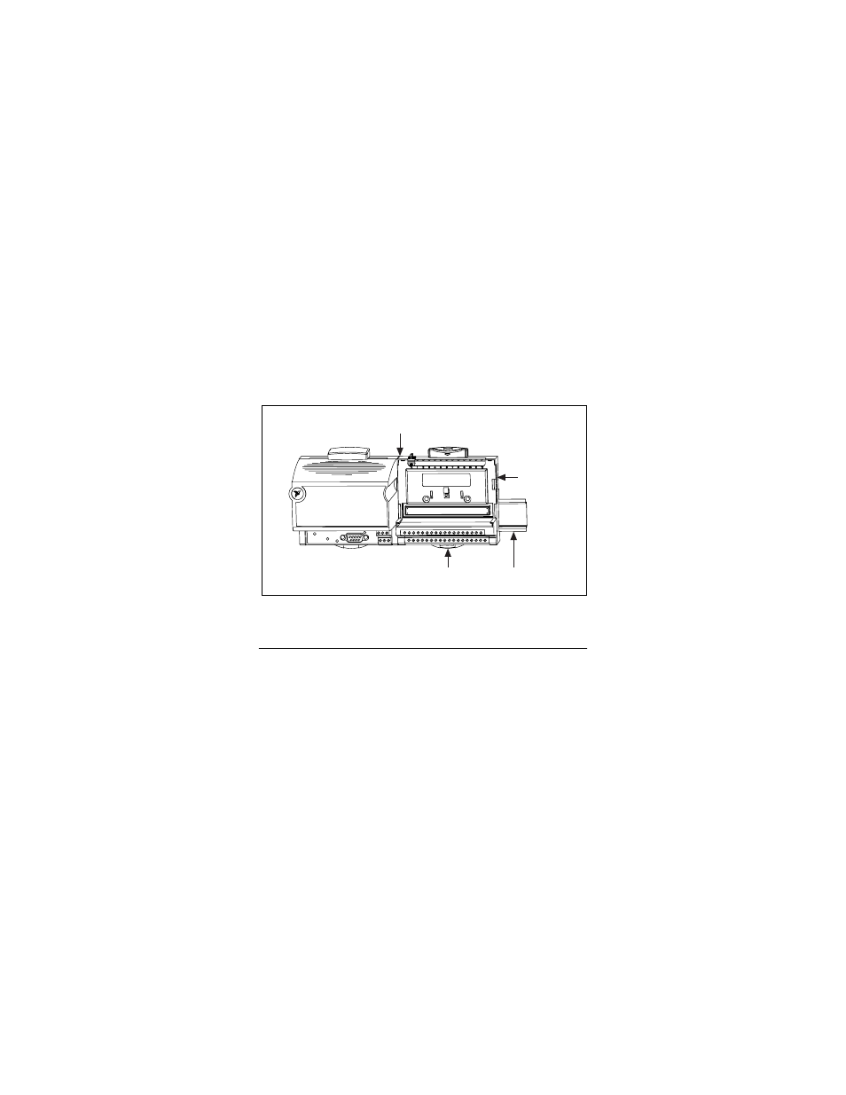
4. Place the protective cover over the local bus connector of the
last terminal base in the bank. Figure 4 shows an installed
FP-1600 network module on a DIN rail.
Figure 4. Installed Network Module
Network Connection
Connect the FP-1600 to an Ethernet network using the RJ-45
Ethernet port on the FP-1600. Connect the RJ-45 Ethernet port
of the FP-1600 to an Ethernet hub using a standard Category 5
Ethernet cable. You can also connect an FP-1600 directly to a
computer using an Ethernet crossover cable. Do not use a cable
longer than 100 m. Figure 5 shows the power and Ethernet
connectors on the FP-1600.
Protective
Cover
Local Bus Connectors
Firmly Mated
Rail Clip
Locked
DIN
Rail