Step action drawing, Rj45 nt1 cable, St interfaces visualink 128 rear nt1 front – NEC VisuaLink 128/384 User Manual
Page 48: Nt1 rear u interface
Page 4-20
NDA-24230 Issue 2.0
Chapter 4
VisuaLink 128/384 User Guide
21.
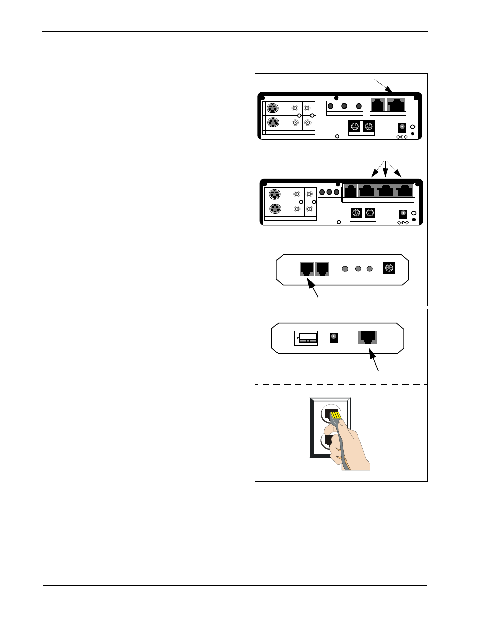
Locate the network cable (RJ45-RJ45) and
connect one end to the S/T LINE port of the
VisuaLink 128 or VisuaLink 384. Connect the
other end of the network cable into the S/T
interface of the NT1.
Note: RJ45-RJ45 cable that is included with the
NT1 unit should be used.
22.
Note 1: RJ45-RJ45 cable that is included with the
NT1 unit should be used.
Note 2: If connecting a VisuaLink 384 system,
Step 21 will have to be repeated three (3)
times.
STEP
ACTION
DRAWING
+
+
+
+
+
DC IN 5V
+
-
Serial1 Serial2/RMT
O
U
T
I
N
VIDEO2 VIDEO1 AUDIO
+
+
TEL
S/T LINE
MIC1
MIC2
MIC3
RJ45 NT1 Cable
S/T
S/T
L-BK LINE PWR
DIN
INTERFACE
ST Interfaces
VisuaLink 128 Rear
NT1 Front
+
+
+
+
+
DC IN 5V
+
-
Serial1 Serial2/RMT
O
U
T
I
N
VIDEO2 VIDEO1 AUDIO
+
+
TEL S/T LINE 1 S/T LINE 2 S/T LINE 3
MIC1 MIC2 MIC3
VisuaLink 384 Rear
RJ45 NT1 Cable
1 2 3 4 5
ON
POWER
U
NT1 Rear
U Interface