National Instruments NI USB-9219 User Manual
Page 18
NI USB-9219 User Guide and Specifications
18
ni.com
Overvoltage protection
Terminals 1 and 2 ............................±30 V
Terminals 3 through 6,
across any combination ...................±60 V
Input impedance
Voltage and Digital In modes
(±60 V, ±15 V, ±4 V) ......................1 M
Ω
Current mode ...................................< 40
Ω
All other modes ...............................>1 G
Ω
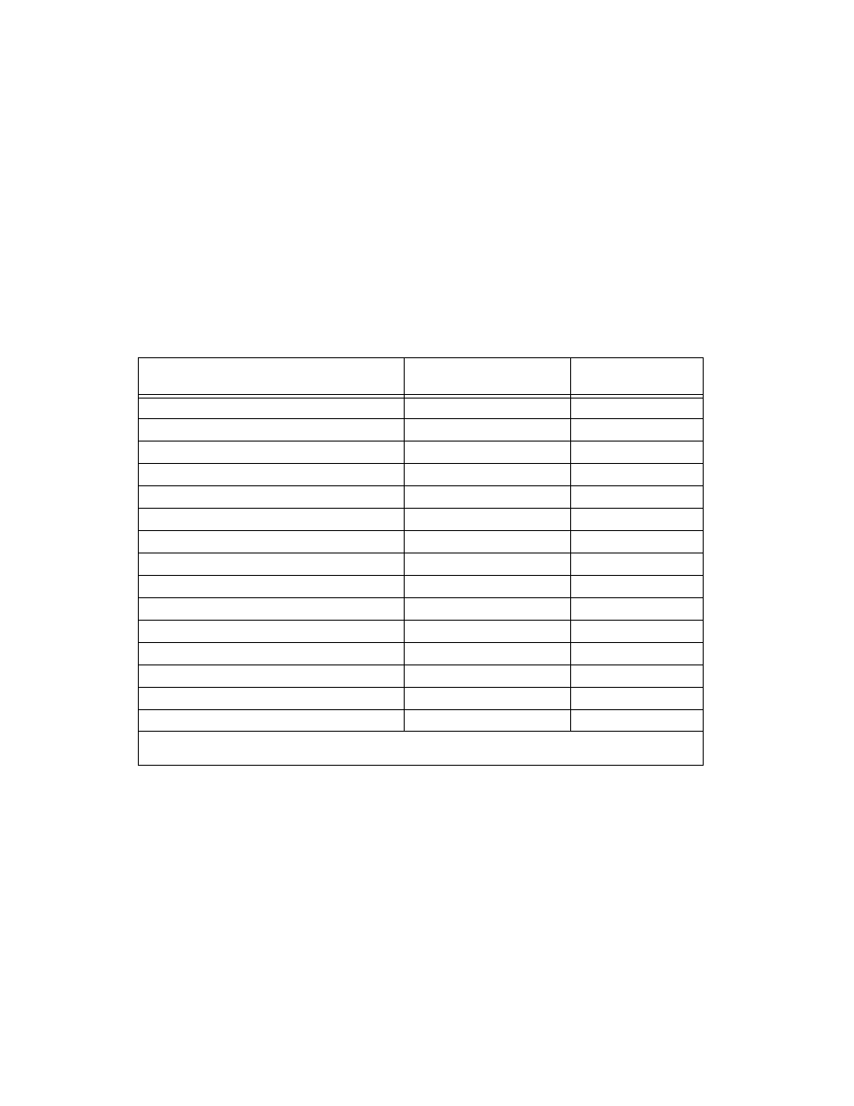
Accuracy
Cold-junction compensation
sensor accuracy.......................................±1°C typ
Mode, Range
Gain Error
(% of Reading)
†
Offset Error
(ppm of Range)
†
Voltage,
±
60 V
±0.3, ±0.4
±20, ±50
Voltage,
±
15 V
±0.3, ±0.4
±60, ±180
Voltage,
±
4 V
±0.3, ±0.4
±240, ±720
Voltage,
±
1 V
±0.1, ±0.18
±15, ±45
Voltage/Thermocouple,
±
125 mV
±0.1, ±0.18
±120, ±360
Current,
±
25 mA
±0.1, ±0.6
±30, ±100
4-Wire and 2-Wire
*
Resistance, 10 k
Ω
±0.1, ±0.5
±120, ±320
4-Wire and 2-Wire
*
Resistance, 1 k
Ω
±0.1, ±0.5
±1,200, ±3,200
4-Wire and 3-Wire RTD, Pt 1,000
±0.1, ±0.5
±240, ±640
4-Wire and 3-Wire RTD, Pt 100
±0.1, ±0.5
±2,400, ±6,400
Quarter-Bridge, 350
Ω
±0.1, ±0.5
±2,400, ±6,400
Quarter-Bridge, 120
Ω
±0.1, ±0.5
±2,400, ±6,400
Half-Bridge,
±
500 mV/V
±0.03, ±0.07
±300, ±450
Full-Bridge,
±
62.5 mV/V
±0.03, ±0.08
±300, ±1,000
Full-Bridge,
±
7.8 mV/V
±0.03, ±0.08
±2,200, ±8,000
*
2-Wire Resistance mode accuracy depends on the lead wire resistance. This table assumes 0
Ω of lead wire resistance.
† Typ (25 °C, ±5 °C), Max (–40 to 70 °C)