Figure 3. relay output circuit, Figure 4. maximum current vs. dc volts, Contact protection for inductive loads – National Instruments FP-RLY-420 User Manual
Page 5
© National Instruments Corp.
5
FP-RLY-420
Figure 3 shows the diagram of one channel’s relay output circuit.
Figure 3. Relay Output Circuit
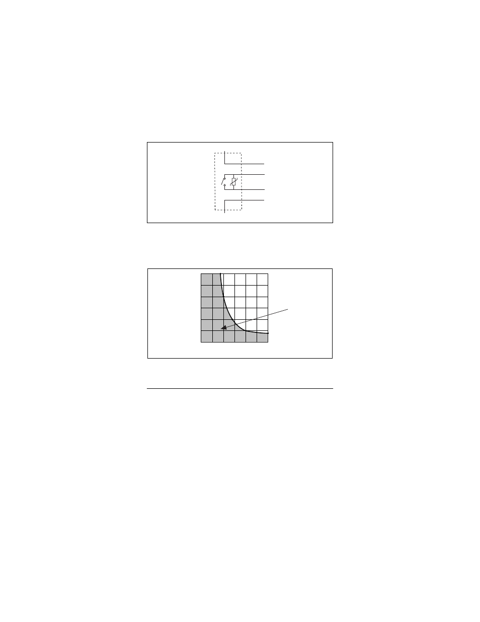
The maximum switching capacity of each relay is 3 A up to
250 VAC or 35 VDC. To switch greater DC voltages, refer to
Figure 4.
Figure 4. Maximum Current vs. DC Volts
Contact Protection for Inductive Loads
When inductive loads are connected to the relays, a large
counter-electromotive force may occur at relay switching time
because of the energy stored in the inductive load. These flyback
voltages can severely damage the relay contacts and greatly
shorten the life of the relay.
It is best to limit these flyback voltages at your inductive load by
installing, across your inductive load, a flyback diode for DC loads
or a metal oxide varistor (MOV) for AC loads. Refer to the next
section,
Guidelines for Selecting Contact Protection Circuits
, for
more information.
N.O.
I.C.
COM
C
V
V
sup
20
0
40
60
DC Volts
Current
(Amps)
80
100 120
.5
1
1.5
2
2.5
3
Safe Operating
Region