Figure 3-1. ni pci-1410 parts locator diagram, Figure 3-2. bnc connector pin assignment, Digital i/o connector – National Instruments Monochrome Image Acquisition Device NI 1410 User Manual
Page 20: Digital i/o connector -2
Chapter 3
Signal Connections
3-2
ni.com
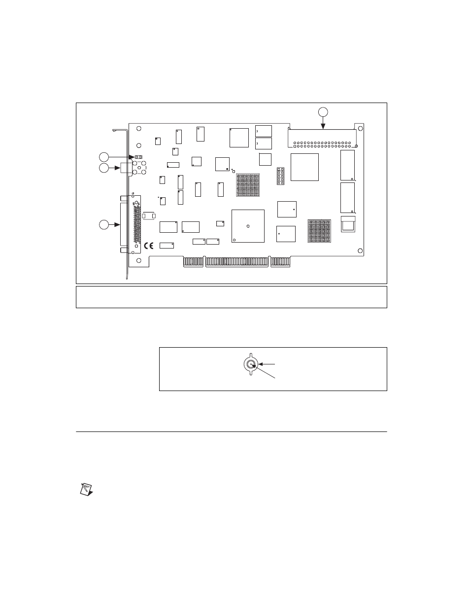
Figure 3-1. NI PCI-1410 Parts Locator Diagram
Figure 3-2 shows the BNC connector pin assignments.
Figure 3-2. BNC Connector Pin Assignment
Digital I/O Connector
The 68-pin VHDCI connector connects to all video signals (VIDEO0,
VIDEO1, VIDEO2, and VIDEO3), the external digital I/O lines, triggers,
and external signals. To access these connections, you can build your own
custom cable or use one of the optional National Instruments cables.
Note
If you are using the VIDEO0 connection on the 68-pin VHDCI connector, you must
unplug the BNC cable.
1
68-Pin VHDCI Connector
3
W1 Jumper
2
BNC Connector
4
RTSI Bus Connector
4
3
1
2
NI PCI-1410
COPYRIGHT 2004
NA
TIONAL INSTR
UMENTS
©
GND
VIDEO0+
See also other documents in the category National Instruments Hardware:
- Instrument Driver NI-DMM (12 pages)
- 24-Bit Half/Full-Bridge Analog Input Module NI 9237 (36 pages)
- NI PXIe-8105 (76 pages)
- PXI NI 5401 (60 pages)
- Fieldpoint CFP-2210 (38 pages)
- NI 781xR (48 pages)
- NI 6233 (180 pages)
- 6508 PCI-DIO-96 (93 pages)
- PXI/CompactPCI Embedded Computer NI PXI-8108 (83 pages)
- NI 9233 (34 pages)
- NI USB-9219 (25 pages)
- GPIB-PC (262 pages)
- cFP-RTD-122 (15 pages)
- USB device 625x (23 pages)
- Isolated Analog Input Modules SCC-AI01 (18 pages)
- NI PCI-6111 (118 pages)
- NI USB-6008 (32 pages)
- PC-DIO-24 (75 pages)
- NI 9474 (31 pages)
- NI 6013 (109 pages)
- PXI-1428 (46 pages)
- NI PCI-5911 (51 pages)
- 2 SD Card Memory Module NI 9802 (16 pages)
- cFP-20xx (24 pages)
- NI USB-9234 (23 pages)
- NI 9871 (24 pages)
- Interface Device NI PCI-1426 (35 pages)
- AT E Series (184 pages)
- 9211A (19 pages)
- Module NI PXI-8250 (39 pages)
- 8330 Series (30 pages)
- NI PXIe-8360 (40 pages)
- Deterministic Ethernet Expansion Chassis NI 9144 (65 pages)
- NI 6509 (23 pages)
- NI MATRIXx Xmath (127 pages)
- NI 9481 (23 pages)
- VXI-1394 (74 pages)
- NI PXI-8104 (69 pages)
- NI 9235 (38 pages)
- 370620B-01 (17 pages)
- FP-RTD-124 (15 pages)
- VXI-USB (61 pages)
- NI PCI-8254R (45 pages)
- Interface Device NI PCI-8254R (16 pages)