Transmission line effects, Transmission line effects -14 – National Instruments NI CVS-1450 Series User Manual
Page 62
Chapter 4
Digital I/O Functionality
NI CVS-1450 Series User Manual
4-14
ni.com
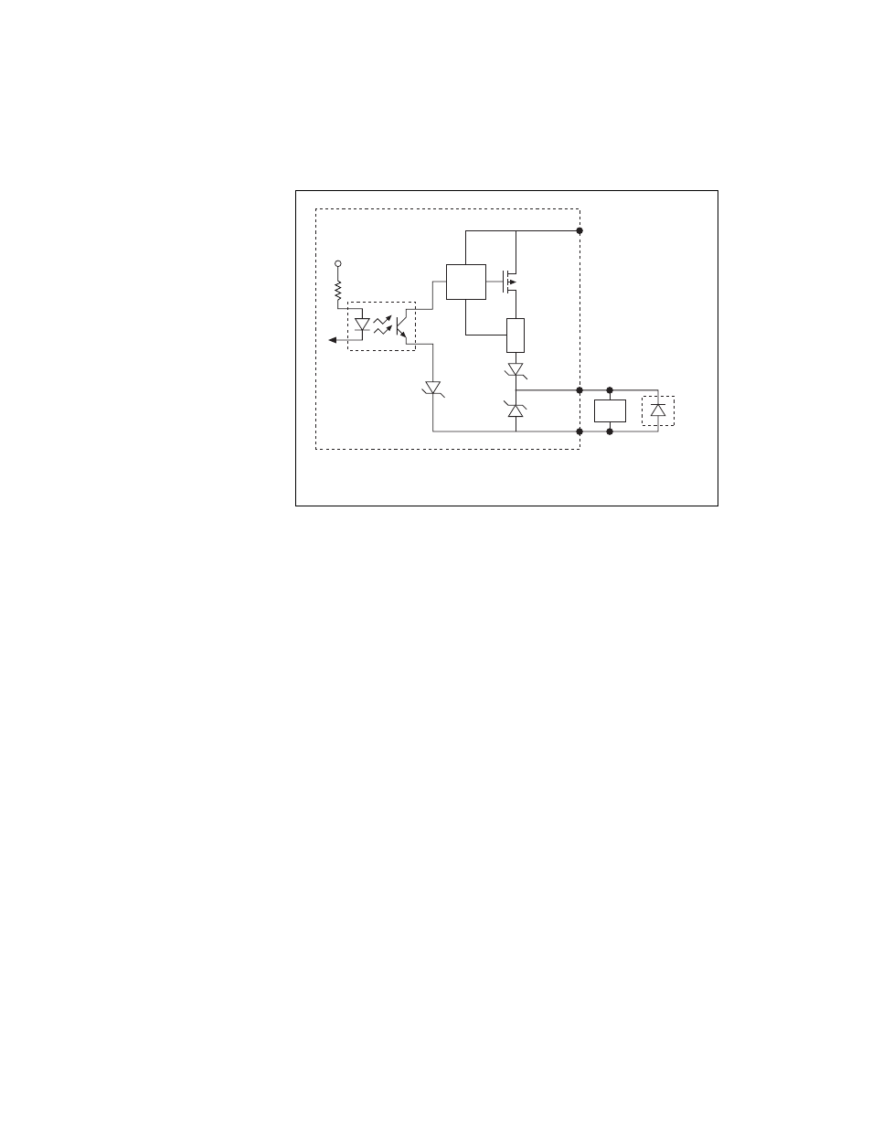
Figure 4-7. Example of Using an External Flyback Diode for Inductive Loads
Transmission Line Effects
Transmission line effects can degrade the signals on the I/O cables and
cause instability. To minimize transmission line effects, use twisted-pair
wires with a characteristic impedance of 118
Ω to connect external signals
to the 44-pin I/O DSUB connector. Use a 75
Ω coaxial cable, such as
RG-179, to connect to the SMB connectors.
Figure 4-8 shows connections to the 44-pin DSUB connector and the
TRIG 0 SMB connector that minimize transmission line effects.
Digital
Output
Viso
Ciso
Vcc
CVS-1450 device
External
Flyback
Diode for
Inductive Loads
Load
See also other documents in the category National Instruments Computer Accessories:
- R Series Intelligent DAQ PXI-784xR (14 pages)
- 7344 (66 pages)
- Relay Module SCC-RLY01 (9 pages)
- Compact FieldPoint Mounting Accessories cFP-21xx (10 pages)
- PCI-4451 (115 pages)
- NI 6239 (172 pages)
- SCXI-1190 (54 pages)
- SCXI-1190/1191 (45 pages)
- NI 785xR (74 pages)
- DIO 6533 (125 pages)
- Multisystem eXtension Interface NI PCIe-836x (37 pages)
- GPIB-BUF (40 pages)
- 6527 (47 pages)
- PCI-8336 (43 pages)
- PXI NI PXI-8105 (73 pages)
- 6025E (136 pages)
- NI 78xxR (12 pages)
- PCI-6110E/6111E (113 pages)
- NI 6115/6120 (127 pages)
- 1128 (97 pages)
- 800 Series (104 pages)
- NI 6115 (127 pages)
- NI 784xR (74 pages)
- GPIB-100A (43 pages)
- VXI-MIO Series (151 pages)
- Low-Cost Multifunction I/O Board for ISA Lab-PC+ (211 pages)
- PC-DIO-24/PnP (107 pages)
- PC-LPM-16/PnP (125 pages)
- NI 7831R (71 pages)
- 653X (147 pages)
- VXI/VME 600 (61 pages)
- PXI NI PXI-1052 (70 pages)
- PC-DIO-96 (105 pages)
- NI UES-3880 (14 pages)
- GPIB-COM (56 pages)
- Switch Executive (8 pages)
- AT-MIO-16X (330 pages)
- 7340 PCI (67 pages)
- NI 783xR (73 pages)
- SCXI-1321 (16 pages)