Input switch setting, Inst alla tion – Niles Audio SI-1230 User Manual
Page 21
Bridging Two Channels Into One (continued)
BusMatrix
TM
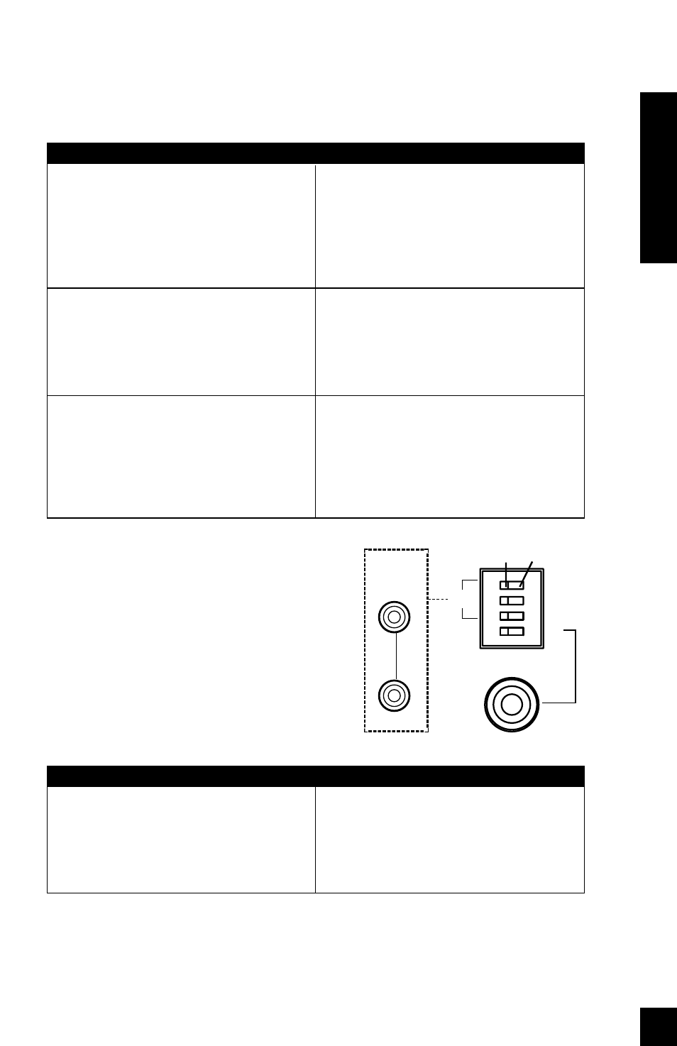
Input Switch Setting
Each channel has a dedicated BusMatrix DIP
switch that assigns that channel’s source. To
assign a signal from the Main Bus Input, select
one of the first three switches which will give
you either Left (L), Right (R) or Mono (L+R). To
assign the channel’s dedicated input select the
fourth switch. Only ONE switch should be
selected to the “ON” position.
20
STEP
1. Move only ONE switch to the "ON"
position for each channel.
DESCRIPTION
CAUTION!
The DIP switch physically allows
you to move all four of the switches to the
“On” position. If you accidentally set more
than one switch "On", you will create an
undesirable mix of inputs on the entire bus.
STEP
2. Connect the speaker wires to the
two Bridged speaker terminals
(BRIDGED +, BRIDGED -). Observe
proper polarity markings.
CAUTION! DO NOT connect a speak-
er selector or headphone junction
box to the output of a bridged
channel pair.
3. Use the EVEN NUMBERED input,
input DIP switch, and level control for
connections and configuration.
DESCRIPTION
Connect your speaker wire only to the red
terminals of the two adjacent amplifier
channels. If one of the speaker wires touch-
es a black terminal (thereby grounding the
red "hot" terminals) you will short circuit
the amplifier.
These connections to a bridged channel
pair will result in either thermal shutdown
or poor quality sound.
When two channels are bridged into one,
make sure that the odd numbered input
DIP switches are all in the “off” position.
INST
ALLA
TION
L
R
L+R
1
BUS
CASCADE
BUS
OUTPUT
L
R
“ON” Position
“OFF” Position
MAIN
BUS
INPUT
L
R