Figure 3-5, Signal connections for solid-state relays -10 – National Instruments DAQ 6527 User Manual
Page 26
Chapter 3
Signal Connections
3-10
www.ni.com
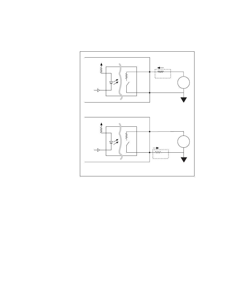
Figure 3-5. Signal Connections for Solid-State Relays
Writing a 0 (logic low) to an output bit closes the relay, and writing a 1
(logic high) opens the relay.
To both sink and source current with one channel requires an external
resistor. You can use the solid-state relays of a 6527 device with external
resistors to drive voltages at TTL or non-TTL levels, from -60 to 60 VDC
or 30 VAC (42 V peak).
For isolated power, total current on all channels exceeding 1 A, or voltages
other than +5 V, you can provide an external power supply. For driving
non-isolated +5 V outputs totaling less than 1 A—for example, when using
the 6527 as a TTL-level output device—you can use the +5 V line from the
6527 device as your voltage source.
Load
R
S
I
f
+5 V
Supply
+
–
Isolation
Isolated
Ground
Digital
Logic
390
Ω
DIG+
6527
DIG–
Load
R
S
I
f
+5 V
Supply
+
–
Isolation
Isolated
Ground
Digital
Logic
390
Ω
DIG+
6527
DIG–
a. Sinking Current
b. Sourcing Current
35
Ω
35
Ω
LH1546
LH1546