Reducing the forward current for high voltages, Solid-state relay outputs, Output channels – National Instruments DAQ 6527 User Manual
Page 25: Reducing the forward current for high voltages -9, Solid-state relay outputs -9, Output channels -9, Figure 3-4, Reducing input current for high voltage signals -9
Chapter 3
Signal Connections
© National Instruments Corporation
3-9
Reducing the Forward Current for High Voltages
As input voltage increases above 5 V, the input current drawn by the 6527
(forward current I
F
) also rises. At 24 V, for example, current is
approximately (24 V – 1.5 V)/3 k
Ω
= 7.5 mA per line.
If you wish to reduce the current and power the 6527 draws—to reduce the
impact on a circuit you are monitoring, for example—you can add another
resistor in series with the 3 k
Ω
current-limiting resistor on the 6527. It is
recommended you choose a resistance value allowing at least 1 mA to flow
through the LED. Assume a maximum drop across the LED of 1.5 V. For
example, for 24 V inputs you could use a resistance of up to
(24 V – 1.5 V)/1 mA – 3 k
Ω
≈
20 k
Ω
for R
S
.
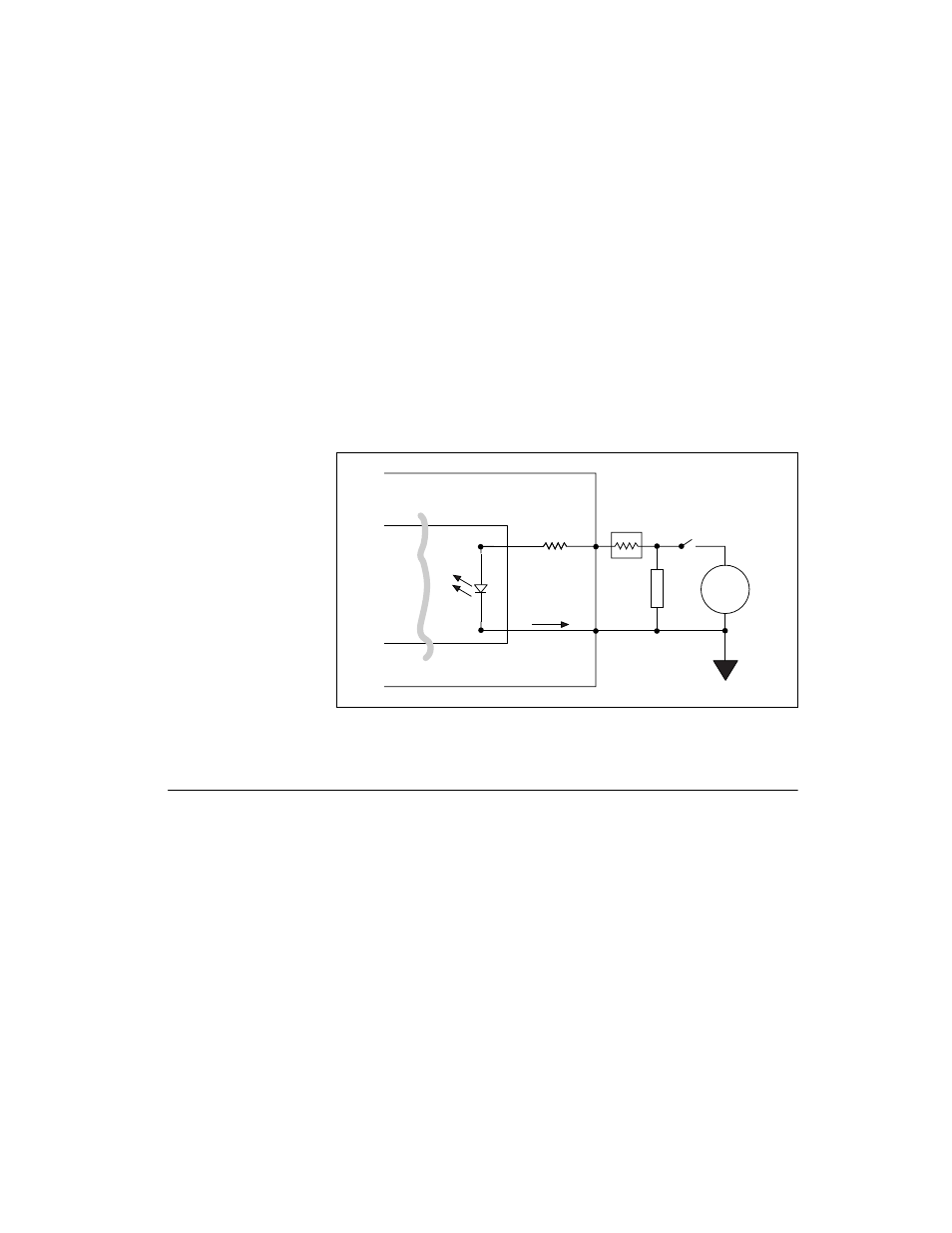
Figure 3-4. Reducing Input Current for High Voltage Signals
Solid-State Relay Outputs
On a 6527 device, I/O connector pins 51 through 98 shown in Figure 3-1
represent the terminals of the solid-state relays.
Output Channels
The output channels of a 6527 device are solid-state relays containing an
LED and two MOSFETs connected together to form a bidirectional switch.
Depending on how the load is connected to the terminals, an output can
either source or sink currents.
Figure 3-5 shows two signal connection examples for driving a load with
these solid-state relays.
0.25 W
6527
Isolation
3 k
Ω
Load
DIG+
DIG–
Supply
Isolated Ground
R
s
I
f
+
–