Description, Features, Pin configurations – Philips SCC2691 User Manual
Page 2
Philips Semiconductors
Product data sheet
SCC2691
Universal asynchronous receiver/transmitter (UART)
2
2006 Aug 04
DESCRIPTION
The Philips Semiconductors SCC2691 Universal Asynchronous
Receiver/Transmitter (UART) is a single-chip CMOS-LSI
communications device that provides a full-duplex asynchronous
receiver/transmitter. It is fabricated with Philips Semiconductors
CMOS technology which combines the benefits of high density and
low power consumption.
The operating speed of the receiver and transmitter can be selected
independently as one of 18 fixed baud rates, a 16X clock derived
from a programmable counter/timer, or an external 1X or 16X clock.
The baud rate generator and counter/timer can operate directly from
a crystal or from external clock inputs. The ability to independently
program the operating speed of the receiver and transmitter make
the UART particularly attractive for dual-speed channel applications
such as clustered terminal systems.
The receiver is quadruple buffered to minimize the potential of
receiver overrun or to reduce interrupt overhead in interrupt driven
systems. In addition, a handshaking capability is provided to disable
a remote UART transmitter when the receiver buffer is full.
The UART provides a power-down mode in which the oscillator is
frozen but the register contents are stored. This results in reduced
power consumption on the order of several magnitudes.
The UART is fully TTL compatible and operates from a single +5V
power supply.
FEATURES
•
Full-duplex asynchronous receiver/transmitter
•
Quadruple buffered receiver data register
•
Programmable data format:
– 5 to 8 data bits plus parity
– Odd, even, no parity or force parity
– 1, 1.5 or 2 stop bits programmable in 1/16-bit increments
•
16-bit programmable Counter/Timer
•
Baud rate for the receiver and transmitter selectable from:
– 22 fixed rates: 50 to 115.2K baud
– Non-standard rates to 115.2 kb
– Non-standard user-defined rate derived from programmable
timer/ counter
– External 1X or 16X clock
•
Parity, framing, and overrun detection
•
False start bit detection
•
Line break detection and generation
•
Programmable channel mode
– Normal (full-duplex)
– Automatic echo
– Local loopback
– Remote Loopback
•
Multi-function programmable 16-bit counter/timer
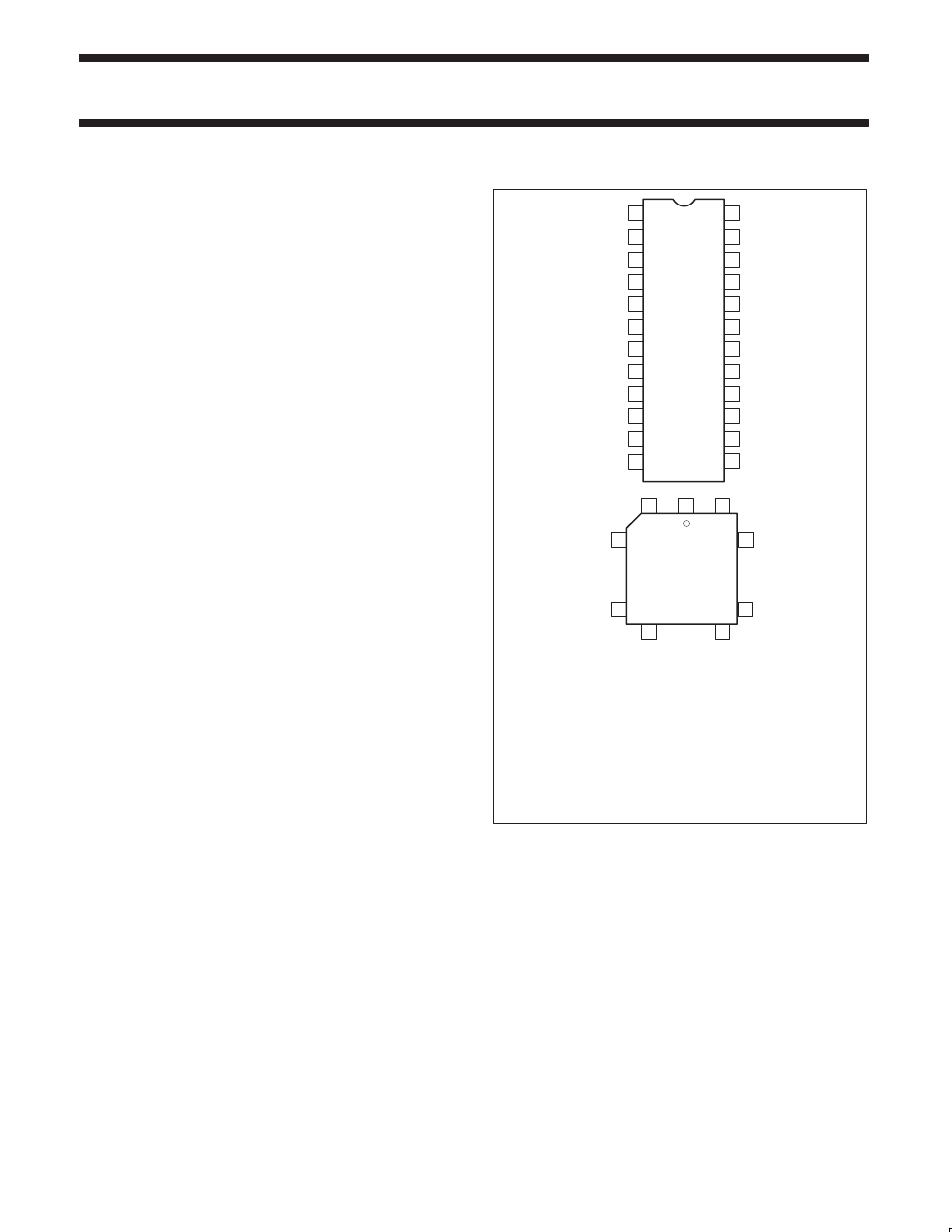
PIN CONFIGURATIONS
1
2
3
4
5
6
7
8
9
10
11
12
23
22
21
20
19
18
17
16
15
14
13
RDN
RxD
TxD
MPO
MPI
A2
A1
A0
X1/CLK
X2
RESET
GND
4
1
26
25
19
18
12
11
5
N24
AND
D24
PACKAGES
A28
PACKAGE
24
V
CC
WRN
D0
D1
D2
D3
D4
D5
D6
D7
CEN
INTRN
Pin
Symbol
Pin
Symbol
V
CC
RDN
RxD
TxD
MPO
MPI
NC
NC
A2
A1
A0
X1/CLK
X2
RESET
1
2
3
4
5
6
7
8
9
10
11
12
13
14
15
16
17
18
19
20
21
22
23
24
25
26
27
28
GND
INTRN
CEN
D7
D6
D5
D4
D3
NC
D2
D1
NC
D0
WRN
SD00122
Figure 1. Pin Configurations
•
Single interrupt output with seven maskable interrupting
conditions
•
On-chip crystal oscillator
•
Low power mode
•
TTL compatible
•
Single +5V power supply
•
Commercial (0
°
C to +70
°
C) and industrial (-40
°
C to +85
°
C)
temperature versions available
•
SOL, PLCC and 300 mil wide DIP packages available