Engine – Poulan 177110 User Manual
Page 18
18
V-BELTS
Check V-belts for deterioration and wear
after 100 hours of operation and replace
if necessary. The belts are not adjustable.
Replace belts if they begin to slip from
wear.
TRANSAXLE COOLING
Keep transaxle free from build-up of dirt
and chaff which can restrict cooling.
TEMPERATURE RANGE ANTICIPATED BEFORE NEXT OIL CHANGE
SAE VISCOSITY GRADES
-20°
0°
30°
40°
80°
100°
-30°
-20°
0°
20°
30°
40°
°
F
°
C
32°
-10°
10°
60°
5W-30
SAE 30
ENGINE
LUBRICATION
Only use high quality detergent oil rated
with API service classification SF, or SJ.
Select the oil’s SAE viscosity grade
according to your expected operating
temperature.
Change the oil after every 25 hours of
operation or at least once a year if the
tractor is not used for 25 hours in one
year.
Check the crankcase oil level before
starting the engine and after each eight
(8) hours of operation. Tighten oil fill cap/
dipstick securely each time you check the
oil level.
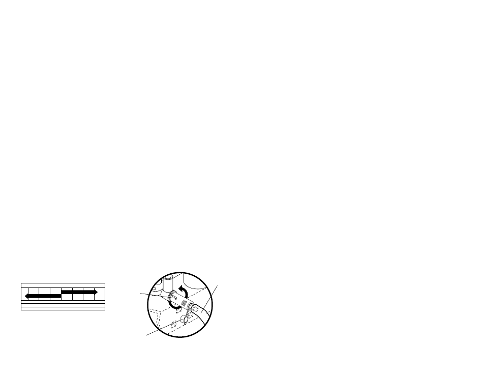
TO CHANGE ENGINE OIL
Determine temperature range expected
before oil change. All oil must meet API
service classification SF-SJ.
• Be sure tractor is on level surface.
• Oil will drain more freely when warm.
• Catch oil in a suitable container.
•
Remove oil fill cap/dipstick. Be careful
not to allow dirt to enter the engine
when changing oil.
•
Remove cap from end of drain valve
and install the drain tube onto the
fitting.
•
Unlock drain valve by pushing inward
slightly and turning counterclockwise.
•
To open, pull out on the drain valve.
•
After oil has drained completely, close
and lock the drain valve by pushing
inward and turning clockwise until the
pin is in the locked position as shown.
•
Remove the drain tube and replace
the cap onto to the end of the drain
valve.
•
Refill engine with oil through oil fill
dipstick tube. Pour slowly. Do not
overfill. For approximate capacity see
“PRODUCT SPECIFICATIONS”
section of this manual.
•
Use gauge on oil fill cap/dipstick for
checking level. Be sure dipstick cap is
tightened securely for accurate
reading. Keep oil at “FULL” line on
dipstick.
Closed
and
Locked
Position
Oil Drain Valve
Cap
Drain
Tube
• Keep battery and terminals clean.
• Keep battery bolts tight.
• Keep small vent holes open.
• Recharge at 6-10 amperes for 1 hour.
NOTE: The original equipment battery on
your tractor is maintenance free. Do not
attempt to open or remove caps or covers.
Adding or checking level of electrolyte is
not necessary.
TO CLEAN BATTERY AND TERMINALS
Corrosion and dirt on the battery and
terminals can cause the battery to “leak”
power.
• Open battery box door.
• Disconnect BLACK battery cable first
then RED battery cable and remove
battery from tractor.
• Rinse the battery with plain water and
dry.
• Clean terminals and battery cable ends
with wire brush until bright.
• Coat terminals with grease or petro-
leum jelly.
• Reinstall battery (See “REPLACING
BATTERY" in the SERVICE AND
ADJUSTMENTS section of this
manual).
NOTE: Although multi-viscosity oils
(5W30, 10W30 etc.) improve starting in
cold weather, these multi-viscosity oils
will result in increased oil consumption
when used above 32°F. Check your
engine oil level more frequently to avoid
possible engine damage from running
low on oil.
31
TRACTOR -- MODEL NUMBER 271470
ELECTRICAL
KEY PART
NO. NO.
DESCRIPTION
1
144925
Battery 12 Volt 25 Amp
2
74760412
Bolt, Hex Head 1/4-20 unc x 3/4
8
156417
Case, Battery Mech Hinge
16
153664
Switch, Interlock Push-In
21
166181
Harness, Light Socket (Includes 4152J)
22
4152J
Bulb, Light
24
4799J
Cable, Battery, 6 Gauge, Red, 11"
25
146147
Cable, Battery, 6 Gauge, Red, W/16 Wire
26
175158
Fuse
27
73510400
Nut Keps Hex 1/4-20 UNC
28
4207J
Cable, Ground, 6 Gauge, Black, 12"
29
121305X
Switch, Plunger
30
175566
Switch, Ignition
33
140401
Key, Ignition
40
170217
Harness, Ignition
41
71110408
Bolt, Hex Head, Fin. 1/4-20 x 1/2
42
131563
Cover, Terminal, Red
43
175141
Solenoid
48
140844
Adaptor Ammeter Rectangular
52
141940
Protection Wire Loop
NOTE: All component dimensions given in U. S.
inches 1 inch = 25.4 mm