Patton electronic 2635 User Manual
Page 33
Hardware installation
33
Models 2603, 2621, and 2635 Getting Started Guide
3 • Initial Configuration
4. Re-assemble the case.
The interface cable has been installed, go to section
“Installing the AC power cord”
Installing an interface cable on the IPLink 2635’s V.35 interface port
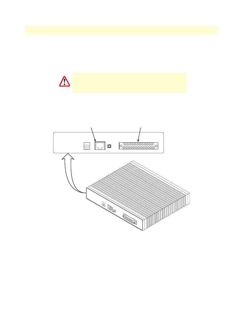
The IPLink Model 2635 comes with a V.35 interface presented on a DB-25 female connector (see
The Model 2635 V.35 (DB-25) interface is configured internally as a DCE. However, when using the Patton
cable with the 2635, the V.35 interface at the M/34 end of the cable is a DTE (see
). In other words,
the Patton DB-25 to M/34 cable is a sync null modem cable.
Figure 10. Rear view of the 2635 showing location of Ethernet and V.35 connectors
The interconnecting cables shall be acceptable for external use
and shall be rated for the proper application with respect to volt-
age, current, anticipated temperature, flammability, and
mechanical serviceability.
CAUTION
MDI-X
Crossover
10/100
Ethernet
Power
MDI-X
Crossover
10/100
Ethernet
WA
N
X.21 Interface
V.35 Interface
Power
V.35 Interface connector
(DB-25)
Ethernet connector
(RJ-45)