Made in china by sunny, Warning, 2 dc power – Patton electronic 2135C User Manual
Page 6
9
4.3.2 DC Power
Supply DC power directly to the power supply jack. DC
power supplied must be +5VDC ±5%, 500mA minimum, center
positive, and can be supplied via a barrel type plug with
2.1/5.5/10mm I.D./O.D./Shaft Length dimensions. For this pow-
ering option, set J3 to position 7 and 8 as shown in figure 4 (fac-
tory default).
The 36-60 VDC DC to DC adapter is supplied with the DC ver-
sion of the Model 2121/2135C. The black and red leads plug
into a DC source (nominal 48VDC) and the barrel power con-
nector plugs into the barrel power supply jack on the
2121/2135C. See Figure 5 below. For this powering option, set
J3 to position 7 and 8 as shown in figure 4 (factory default).
DC power (+5VDC) can also be supplied via pins 14 or 15
on the DB-15 connector for the Model 2121. DC power
(+5VDC) can also be supplied via pins KK or NN on the M/34
connector for the Model 2135C.
To Power
Supply Jack
To -48VDC
Source
-Vin
+Vin
SWITCHING POWER SUPPL
Y
MODEL
: SYD1
106-0505
INPUT
: 36-60V 0.2A
MAX
OUTPUT
: +5V 1.0A
OUTPUT
POWER : 5W MAX
S/N
: G01234567890
MADE IN CHINA
BY
SUNNY
Black lead (-V)
Red lead (+V)
Barrel power connector
WARNING!
There are no user-serviceable parts in the
power supply section of the Model 2121/2135C. For more
information, please contact Patton Electronics Technical sup-
port at (301)975-1007, via our web site at
http://www.patton.com, or by e-mail at [email protected].
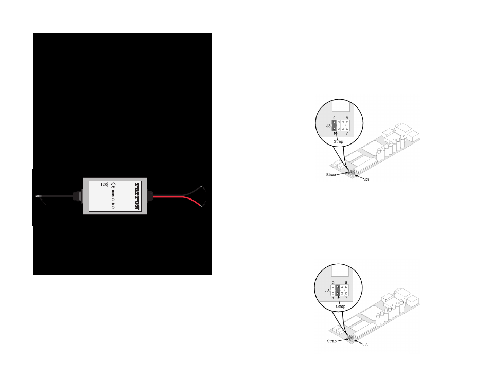
Figure 5: Connecting DC Power to the 2121/2135C DC Power Supply.
Power-up 2121 via DB-15 Connector on Pin 15
Place strap position 1 and 2 on J3 for DC power supply. See
figure 6 below.
Power-up 2135C via M/34 Connector on Pin KK
Place strap position 1 and 2 on J3 for DC power supply.
See figure 6 below.
Power-up 2121 via DB-15 Connector on Pin 14
Place strap position 3 and 4 on J3 for DC power supply. See figure 7
below.
Power-up 2135C via M/34 Connector on Pin NN
Place strap position 3 and 4 on J3 for DC power supply. See figure 7
below.
10
Figure 6. Strap positions 1 and 2 on J3
Figure 7. Strap positions 3 and 4 on J3