Peavey PRO COMM U1002 User Manual
Page 10
10
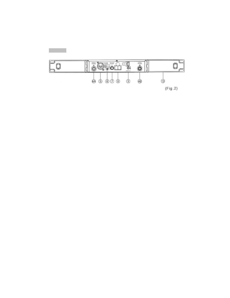
Rear Panel:
(4) Rear Antenna Input Connectors (A/B): Installed with antenna directly. This
connector also provides power for optional antenna booster.
(5) Balanced Audio output Jack: XLR type connector provides a balanced
output signal from the receiver to the mixer.
(6) Line-Level Switch: Used for the selection of either Mic-level or Line-level
output.
(7) Unbalanced Audio output Jack: 1/4" Phone jack provides an unbalanced
signal from the receiver to the mixer or guitar/bass amplifier.
(8) Computer Network Interface connector: Network socket to connect to a
computerized system-monitoring program.
(9) DC Input socket: For 12 volt DC supply. Please note that the polarity of
the center pin in the socket is positive (+),
(10) Rack mount Brackets (OPTIONAL): Allows the installation of the receiver
into an EIA 19" standard rack case.
- PV 215 EQ (24 pages)
- CA-A540B (36 pages)
- CA6-X (2 pages)
- CS 1800G (32 pages)
- CS 4080 HZ (52 pages)
- CC 1800 (84 pages)
- MMA81502 (48 pages)
- PV 1200 (24 pages)
- Impulse 100P (15 pages)
- Q 215FX (20 pages)
- Q431FX (20 pages)
- CS 400x (36 pages)
- TourTM Series (16 pages)
- CPX 900 (2 pages)
- Max 450 (28 pages)
- 50 212 (24 pages)
- IA 10/4 (2 pages)
- JSX 212 (48 pages)
- 646-049 (20 pages)
- Penta 412 (1 page)
- CS 1000X (20 pages)
- CM2208 (64 pages)
- Q (11 pages)
- Classic 50/50 (19 pages)
- ICS 4200 (56 pages)
- IDC 150T II (8 pages)
- JSX Joe Satriani Signature All-Tube Amplifier (36 pages)
- A/A-8P (2 pages)
- Multiplex Series (22 pages)
- IA 800 (69 pages)
- 6505TM (16 pages)
- 6505TM (36 pages)
- 115 (32 pages)
- KB4/KB5 (28 pages)
- Q215B (28 pages)
- Q 231F Dual (20 pages)
- CS 800H (60 pages)
- CS 1200X (22 pages)
- PV 3800 (20 pages)
- CS 8OOX (28 pages)
- Penta Tube Amplifier (32 pages)
- PV 2600 (32 pages)
- 8002 (42 pages)
- CS 3000G (28 pages)