System interconnections, Installation, System interconnection – Polaris D7500 User Manual
Page 12
12
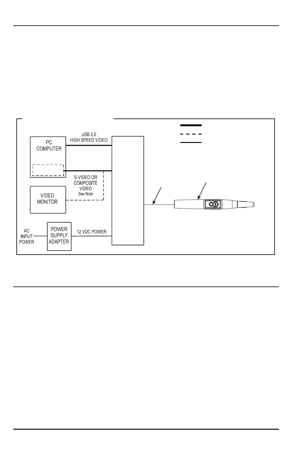
Polaris System - The diagram below shows the possible interconnections
for the Polaris System . The heavy solid connection lines designate the typical
operating configuration (connected to a computer system) . The dashed line shows
the optional connection to a video monitor, while the lighter solid connection lines
show camera and power connections common to all system setups . Connect the
Polaris System as required by individual office equipment .
SYSTEM INTERCONNECTIONS
Installing the Polaris System is as simple as deciding where to place the
Control Module and making the necessary cable connections to a video
monitor and/or a PC loaded with an Air Techniques Authorized DirectX 9
compliant user-supplied streaming video software application such as Visix .
Perform the following procedures to install the Polaris System .
Control Module Location - Locate the Polaris Control Module on a table
top, cart or any flat stable surface convenient to an AC wall outlet and associated
computer system/monitor . It can also be installed hanging under a table top,
under the chair or on the computer using the supplied Dual Lock Fastener Kit .
Make sure that the selected location allows easy access to front and rear panel
controls and connectors .
INSTALLATION
15-Foot
Handpiece
Cable
POLARIS
CAMERA
HANDPIECE
ideo
Capture Card
POLARIS
CONTROL
MODULE
System Interconnection
Typical Connections
Optional Connections
Required Connections
Note:
S-Video and Composite Video cables can
be connected to either a PC computer with
capture card or video monitor as required by
individual office equipment.