Control module functions – Polaris D7500 User Manual
Page 11
11
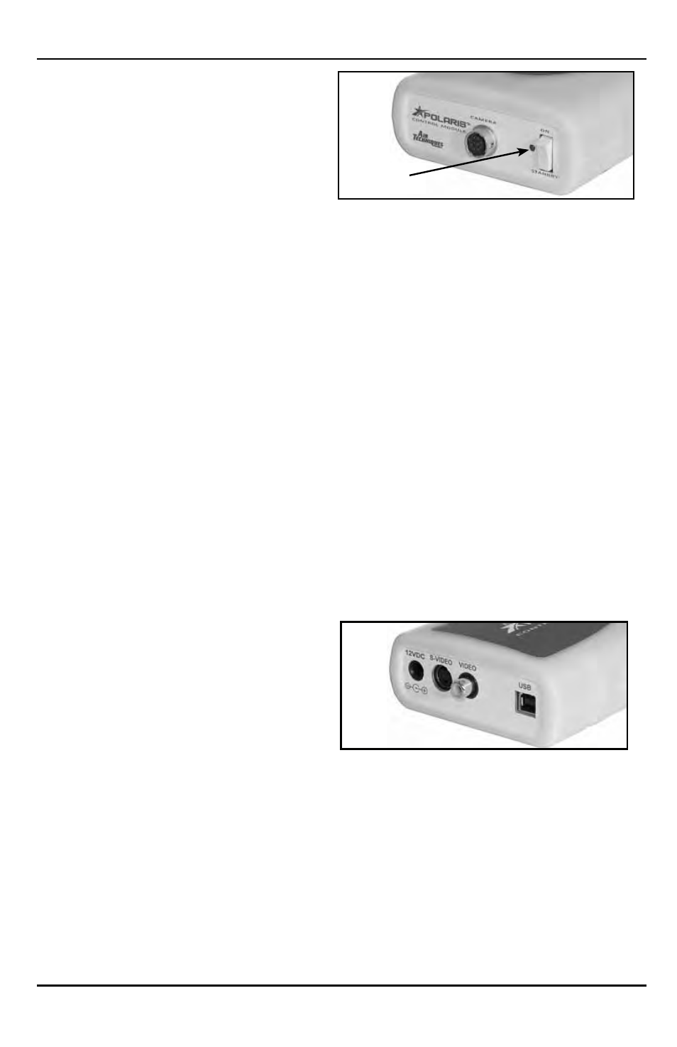
CAMERA Connector
A 10 pin connector socket that accepts con-
nection of the keyed 10-pin quick disconnect
plug end from the multi-conductor Handpiece
cable . Makes connection between the Camera
Handpiece and Control Module to provide power,
video output and control for the camera .
Power Indicator Lamp
A green LED lamp that illuminates to indicate
the presence of 12 VDC operating power from
the power supply adapter .
STANDBY/ON Switch
A rocker panel switch that controls the application
of 12 VDC operating power from the Power Supply
Adapter .
When set in the ON position, the 12 VDC is
applied, the LED power indicator lamp illuminates,
and the camera is operational .
The 12 VDC is removed and the camera is
turned off when the switch is set in the STANDBY
position and the LED power indicator lamp
extinguishes .
Control Module Front Panel
Controls and Indicators
Control Module Rear Panel
Connectors
12 VDC Connector
Provides connection of the 12 VDC operating
power from the Power Supply Adapter .
S-VIDEO Connector
A 4-pin Mini DIN connector that provides output
connection for S-Video peripherals (e .g . video
monitor or computer with capture card) .
VIDEO Connector
An RCA connector that provides connection for
composite video peripherals (e .g . video monitor
or computer with capture card) .
USB Connector
A USB type B connector that provides connection
to the USB 2 .0 High Speed port of the computer .
CONTROL MODULE FUNCTIONS
Power
Indicator Lamp