Aa-a, 2 overall connection diagram(guide page), Fm/am tuner unit – Pioneer DEH-2130R EN User Manual
Page 10: Keyboard unit
10
DEH-2130R,2100R
1
2
3
4
1
2
3
4
D
C
B
A
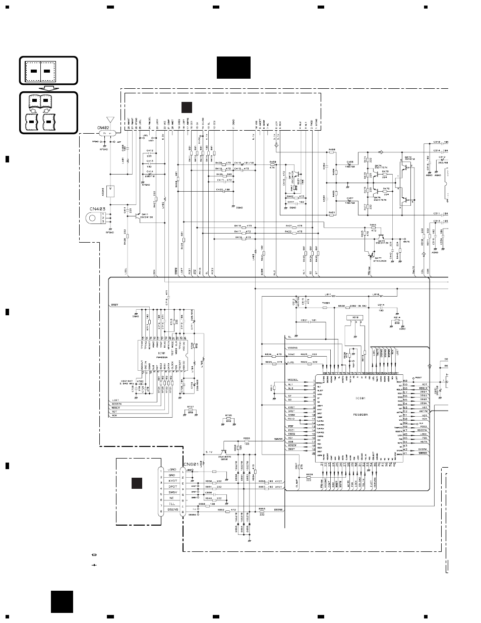
3.2 OVERALL CONNECTION DIAGRAM(GUIDE PAGE)
Note: When ordering service parts, be sure to refer to “EXPLODED VIEWS AND PARTS LIST” or “ELECTRICAL PARTS
LIST”.
A-a
A-b
A-a
A-a
A-b
A-b
A-b
A-b
A-a
A-a
Large size
SCH diagram
Guide page
Detailed page
A
A-a
DSP-201M-S00B
162
162
123
123
272
272
4.194MHz
CSS1047
104
102
0R0
R699
0R0
FM(100%):-15.5dBs
AM (30%):-26dBs
FM/AM TUNER UNIT
For resistors and capacitors in the circuit diagrams, their resistance values or
capacitance values are expressed in codes:
Ex. *Resistors
Code Practical value
123 12k ohms
103 10k ohms
*Capacitors
Code Practical value
103 0.01
µ
F
101/10 100
µ
F/10V
The > mark found on some component parts indicates
the importance of the safety factor of the part.
Therefore, when replacing, be sure to use parts of
identical designation.
Symbol indicates a resistor.
No differentiation is made between chip resistors and
discrete resistors.
NOTE :
Symbol indicates a capacitor.
No differentiation is made between chip capacitors and
discrete capacitors.
SYSTEM CONTROLLER
KEYBOARD
UNIT
B
C