Premio Computer Apollo/Shadowhawk User Manual
Page 94
Technical Reference
71
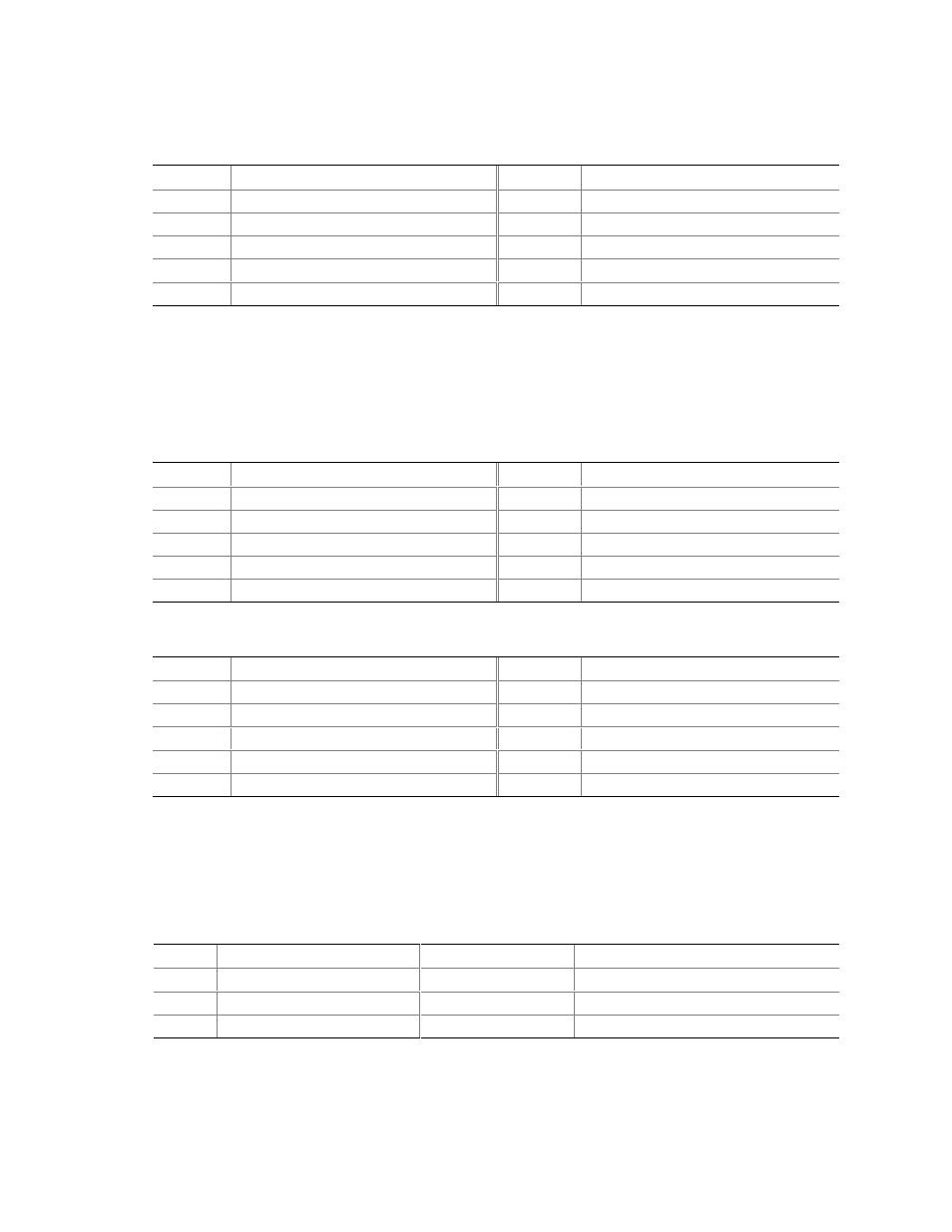
Table 41.
Front Panel Audio Connector
Pin
Signal Name
Pin
Signal Name
1
MIC_IN_FP
2
AUD_JACK_GND
3
MIC_BIAS
4
V_5P0_AUD_ANALOG
5
R_FNTOUT
6
R_RETIN
7
Not connected
8
Not connected
9
L_FNT_OUT
10
L_RETIN
✏
NOTE
The front panel audio connector is alternately used as a jumper block for routing audio signals.
Refer to Section 2.9.1 on page 74 for more information.
Table 42.
Serial Port B Connector (Optional)
Pin
Signal Name
Pin
Signal Name
1
DCD (Data Carrier Detect)
2
RXD# (Receive Data)
3
TXD# (Transmit Data)
4
DTR (Data Terminal Ready)
5
Ground
6
DSR (Data Set Ready)
7
RTS (Request to Send)
8
CTS (Clear to Send)
9
RI (Ring Indicator)
10
Not connected
Table 43.
Front Panel USB Connector
Pin
Signal Name
Pin
Signal Name
1
USB_FNT_PWR
2
USB_FNT_PWR
3
USB_FNTA#
4
USB_FNTB#
5
USB_FNTA
6
USB_FNTB
7
Ground
8
Ground
9
Not connected
10
Not connected
2.8.3.1 Auxiliary Front Panel Power/Sleep/Message-Waiting LED Connector
(Optional)
Pins 1 and 3 of this connector duplicate the signals on pins 2 and 4 of the front panel connector.
Table 44.
Auxiliary Front Panel Power/Sleep/Message-Waiting LED Connector
Pin
Signal Name
In/Out
Description
1
HDR_BLNK_GRN
Out
Front panel green LED
2
Not connected
3
HDR_BLNK_YEL
Out
Front panel yellow LED