Pride Mobility Jet 10 User Manual
Page 18
18
www.pridemobility.com
Jet 10/Rev H/Feb03
I V . Y O U R J E T 1 0
ELECTRICAL CONNECTORS AND COMPONENTS
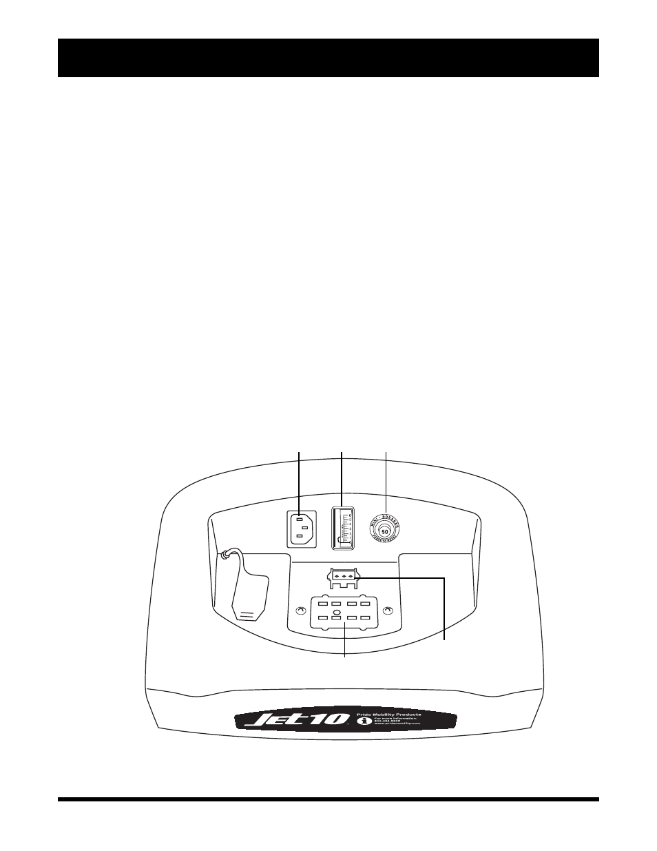
The electrical connectors and components are located on the back of your Jet 10. See figure 4.
n Battery charger AC power cord receptacle: This is where your battery charger power cord plugs in. The
battery charger power cord is not attached to the unit at all times. For more information, see IX. Batteries and
Charging.
n Ammeter: The ammeter displays the chargers current output in amps. For more information, see VIII.
Operation.
n 9-pin Controller Connector: This is where the joystick connects to the motors, batteries, and brakes.
n Charger Connector: This is where the charger connects to the controller.
n Main Circuit Breaker: The main circuit breaker is a safety feature built into your Jet 10. When the batteries
and the motors are heavily strained (e.g., from excessive loads), the main circuit breaker will trip to prevent
damage to the motors and the electronics. If the circuit trips, allow your Jet 10 to rest for approximately one
minute. Then, push in the circuit breaker button, turn on the controller power, and continue normal operation. If
the main circuit breaker continues to trip repeatedly, contact your authorized Pride provider.
Figure 4. Utility Tray
AMMETER
9-PIN CONTROLLER CONNECTOR
BATTERY CHARGER AC
POWER CORD RECEPTACLE
CHARGER CONNECTOR
MAIN CIRCUIT BREAKER