Handling information, Soldering, 2 soldering by dipping or by solder wave – Philips TDA6107AJF User Manual
Page 13: 3 manual soldering, 4 package related soldering information, Tda6107ajf, Philips semiconductors
9397 750 14728
© Koninklijke Philips Electronics N.V. 2005. All rights reserved.
Product data sheet
Rev. 02 — 28 April 2005
13 of 16
Philips Semiconductors
TDA6107AJF
Triple video output amplifier
13. Handling information
Inputs and outputs are protected against electrostatic discharge in normal handling.
However, to be completely safe, it is desirable to take normal precautions appropriate to
handling integrated circuits.
14. Soldering
14.1 Introduction to soldering through-hole mount packages
This text gives a brief insight to wave, dip and manual soldering. A more in-depth account
of soldering ICs can be found in our
Data Handbook IC26; Integrated Circuit Packages
(document order number 9398 652 90011).
Wave soldering is the preferred method for mounting of through-hole mount IC packages
on a printed-circuit board.
14.2 Soldering by dipping or by solder wave
Driven by legislation and environmental forces the worldwide use of lead-free solder
pastes is increasing. Typical dwell time of the leads in the wave ranges from
3 seconds to 4 seconds at 250
°
C or 265
°
C, depending on solder material applied, SnPb
or Pb-free respectively.
The total contact time of successive solder waves must not exceed 5 seconds.
The device may be mounted up to the seating plane, but the temperature of the plastic
body must not exceed the specified maximum storage temperature (T
stg(max)
). If the
printed-circuit board has been pre-heated, forced cooling may be necessary immediately
after soldering to keep the temperature within the permissible limit.
14.3 Manual soldering
Apply the soldering iron (24 V or less) to the lead(s) of the package, either below the
seating plane or not more than 2 mm above it. If the temperature of the soldering iron bit is
less than 300
°
C it may remain in contact for up to 10 seconds. If the bit temperature is
between 300
°
C and 400
°
C, contact may be up to 5 seconds.
14.4 Package related soldering information
[1]
For SDIP packages, the longitudinal axis must be parallel to the transport direction of the printed-circuit
board.
[2]
For PMFP packages hot bar soldering or manual soldering is suitable.
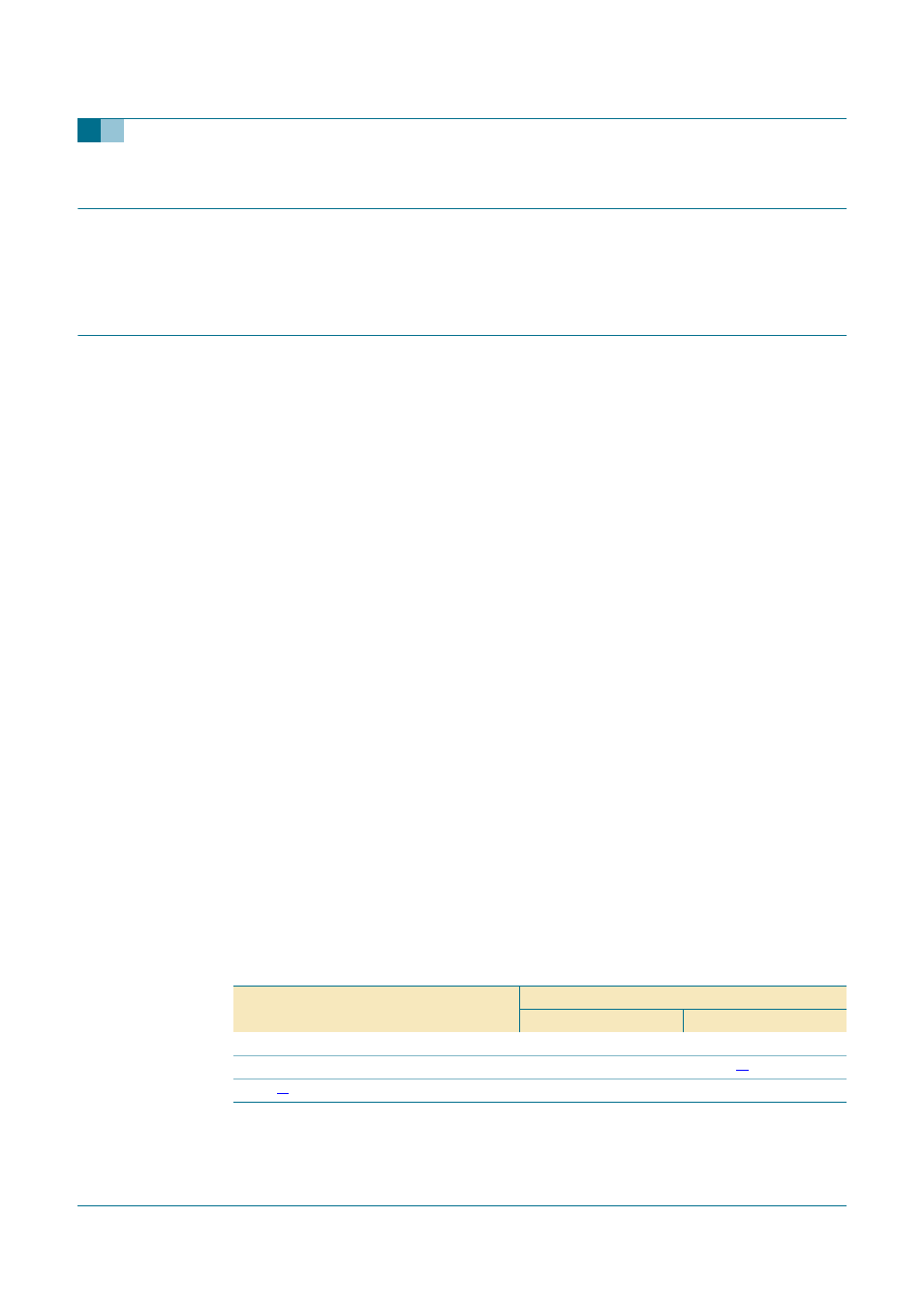
Table 6:
Suitability of through-hole mount IC packages for dipping and wave soldering
methods
Package
Soldering method
Dipping
Wave
CPGA, HCPGA
−
suitable
DBS, DIP, HDIP, RDBS, SDIP, SIL
suitable
suitable
[1]
PMFP
[2]
−
not suitable