Presetting the controls before use, Playing the mixer’s output signal, Connecting the outputs – PYLE Audio 1020 User Manual
Page 4: Connecting the mixer inputs
Presetting the Controls Before Use
Since sudden high output levels from your Pyle Pro mixer can damage not only audio devices connected
to the mixer output but your hearing as well (especially if you are using headphones), please adjust
the mixer’s controls BEFORE connecting AC power or turning on the unit.
Set up the mixer controls like this before you start:
Pyle Pro Mixer Owner’s Manual – 5
4 – Pyle Pro Mixer Owner’s Manual
Playing the Mixer’s Output Signal
To record the mixer’s output signal, connect audio patch cords (not supplied) from the mixer’s REC
(Record) L and R jacks to your tape deck’s left and right input jacks.
To monitor the mixer’s output on a second set of speakers in the DJ booth (or in a remote location),
connect an audio patch cord from the mixer’s ZONE L and R jacks to the additional amplifier’s left
and right input jacks.
Power On/Off
Balance
Gain
Tone Controls, Treble, Mid and Bass
MIC 1/2, CH 1/2/3, Master and Cue Levels
Crossfader
OFF
MID
MID
0
0
CENTER
CONTROL
SETTING
Connecting the Outputs
After presetting the controls (above), you can then connect the mixer’s output jacks to the output
devices’ input jacks. Before connecting these devices, however, be sure to preset their controls to
avoid any damage to your equipment due to unexpected high output levels.
Set the output devices’ controls like this before you start:
Tape Deck
Amplifier/Receiver
OFF
OFF
FLAT
OUTPUT DEVICE
SETTING
CONTROL
POWER
POWER
TONE
To play the mixer’s output signal through your speaker system (for events such as parties, dances,
conferences, etc.) connect an audio patch cord (not supplied) from the mixer’s MASTER L and R jacks
to your receiver’s left and right input jacks. This mixer permits you to choose cables with either RCA
jacks or 1/4” jacks for this connection, but do not use both sets of jacks simultaneously.
Recording the Mixer’s Output Signal
Monitoring the Mixer’s Output signal in the DJ Booth
This mixer permits connection of up to eight (10) audio input sources, including up to two microphones.
Such a system might include, for example:
Two Microphones
Two Turntables
Four CD players
Please observe
the following:
Do not connect any audio source with a HIGH LEVEL
OUTPUT to the LOW LEVEL PHONO 1 or PHONO 2 mixer
audio input jacks (an audio source output with a volume
control is HIGH LEVEL).
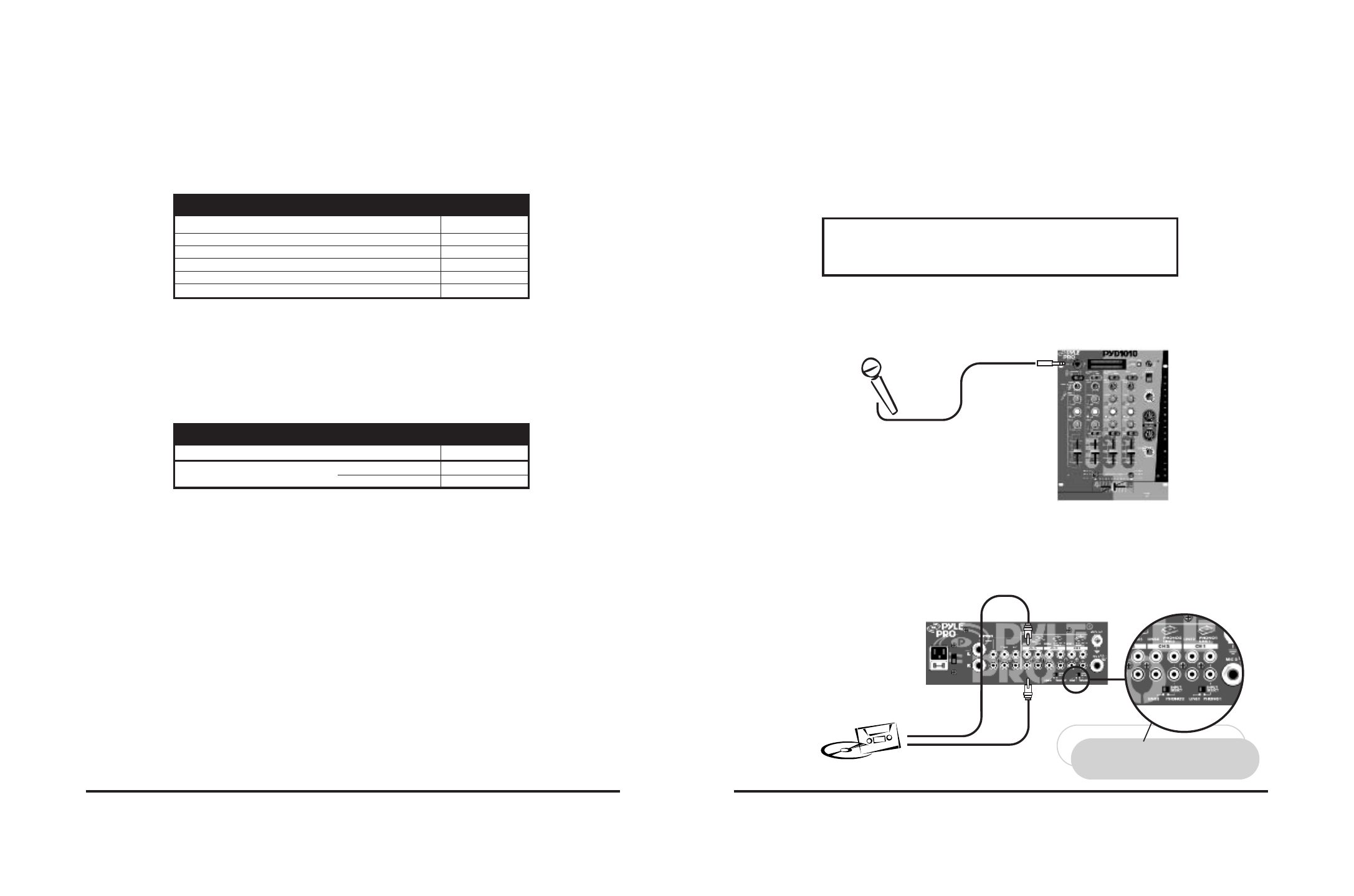
Connect audio inputs as follows:
1. DJ Microphone. Connect the DJ’s MIC 1 (not supplied) to the mic input jack in the upper left
corner of the mixer control panel. The special combo jack permits you to connect with either a 1/4”
plug or XLR plug.
2. High Level Output Audio Sources. Connect up to 6 such sources (tuner, cassette deck, CD
Player, camcorder or VCR) to the input jacks for Line 1 (if not being used as Phono 1 input), Line
2, Line 3 (if not being used as Phono 2 input), Line 4, Line 5 and Line 6. Please note that Phono 1
and Line 1 (as well as Phono 2 and Line 3) use the same jacks. The selector switch(e)s below the
jacks should be set to Line position if the jacks are used for the High Level input sources described
here.
Connecting the Mixer Inputs
High Level Output
Audio Source
CD player, cassette deck, camcorder, VCR, etc.
Use RCA type
patch cables
LEFT output
RIGHT output
If you use a High Level Output Audio Source(s)
in the Phono1/Line1 (and/or Phono2/Line3)
input jack(s), be sure to place the Input Select
switch in the LINE1 (and/or LINE3) position(s)!
CD player, cassette deck, camcorder, VCR, etc.
NOTE!
DJ MIC
Use 1/4” or
XLR-type jack
Two Microphones
Six CD players
Two Microphones
Two Turntables
Two CD players
Two Cassette Decks
Two Microphones
Two Turntables
Two CD players
One Rhythm Synth
One Cassette Deck