Figure 11, Detail 12 figure 12 – ParaBody 426103 User Manual
Page 19
19
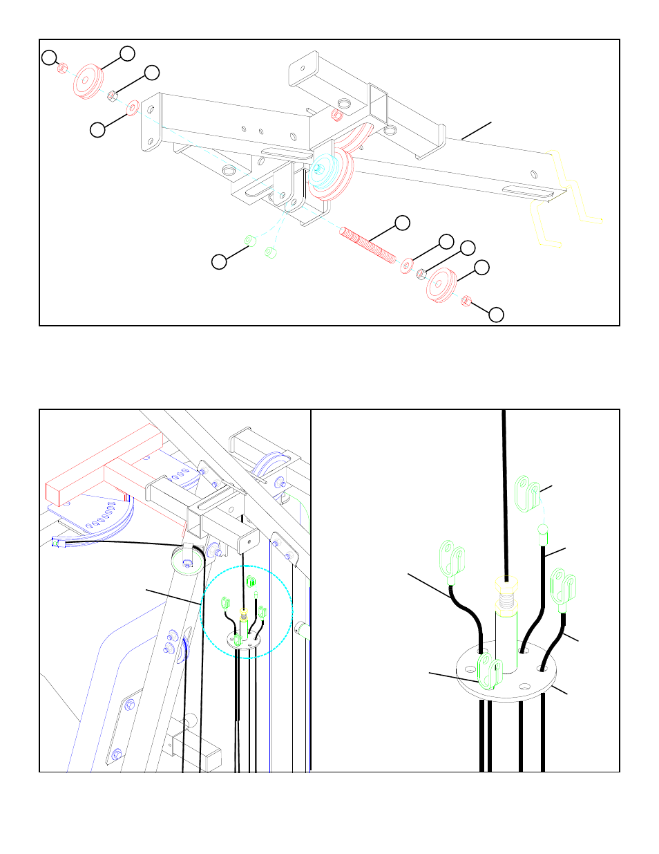
FIGURE 11
STEP 11
STEP 12
• Position two 3/8 X 1/2” SPACERS (2) inside the rear bracket of the TOP BOOM and slide one 3/8” THREAD SHAFT (9) through the
bracket. See FIGURE 11.
TOP BOOM
7
8 3/8” HEX NUT
6
9
8 3/8” HEX NUT
6
5
7
5
• SECURELY assemble two 2” PULLEYS (5) to the rear bracket on the TOP BOOM using one 3/8” THREADED SHAFT (9), two 3/8”
WASHERS, two 3/8” HEX NUTS (8), and two 3/8” LOCK NUTS (7) as shown in FIGURE 11.
2
DETAIL 12
FIGURE 12
SEE DETAIL 12
LEG
CABLE
LAT
CABLE
LEG
PRESS
CABLE
PRESS
CABLE
D-RING
KEYHOLE
CLEVIS
• Run the LEG PRESS CABLE through the correct hole on the d-ring and attach one KEYHOLE CLEVIS to the end of the LEG PRESS
CABLE. See FIGURE 12 & DETAIL 12.
See also other documents in the category ParaBody Sports and recreation:
- Free Weight Systems (5 pages)
- 886101 (3 pages)
- 425/660 (2 pages)
- 822 (9 pages)
- 848101 (14 pages)
- 881 (26 pages)
- Free Weight Smith System (5 pages)
- Leg Press 100101 (14 pages)
- 360101 (11 pages)
- 777 (5 pages)
- 832102 (14 pages)
- Leg Press 100 (11 pages)
- 205101 (1 page)
- 425 (2 pages)
- 440 (33 pages)
- Hip Sled System (24 pages)
- 824 (8 pages)
- 425103 (40 pages)
- GS2 (24 pages)
- 826 (8 pages)
- 856 (6 pages)
- 400101 (27 pages)
- 829 (14 pages)
- 435104 (13 pages)
- GS6 (8 pages)
- 842 (6 pages)
- 778 (13 pages)
- 375101 (22 pages)
- Leg Press 5 (15 pages)
- 838 (10 pages)
- 441101 440 (10 pages)
- LP5 (15 pages)
- Home Guide (9 pages)
- 888 (15 pages)
- cm3 (8 pages)
- 870 (4 pages)
- 893103 (20 pages)
- 890 (10 pages)
- 250101 (18 pages)
- 843 (12 pages)
- GS4 (1 page)
- 849 (7 pages)
- 855 AB (9 pages)
- 883 (31 pages)