PVI Industries PV500-40 User Manual
Page 3
Page 3 / 7
PV500-40 04/2013
1.4 UPPER
LED
READOUT
The default display of this readout is the temperature sensed at Probe 2. Probe 2 may display the tank stored water
temperature, outlet water temperature, flue gas temperature, ambient temperature, remote tank or blended water
temperature, etc., depending on the product and application. Refer to your specific water heaters Installation and
Maintenance Manual and the supplied wiring drawing. The upper LED readout can also be switched to display
Probe 1 or 3 (if used) or the modulation % or the temperature difference between Probe 1 and 2. If Probe 2 is not
utilized, the display will show “nu”.
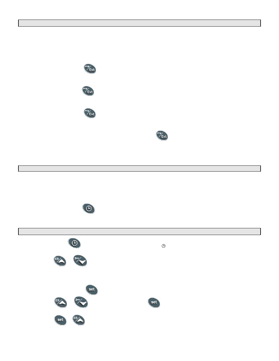
By pressing and releasing the
button once, the Upper LED will display the actual temperature sensed at
Probe 3. Probe 3 (if used) may display the flue gas temperature or outside ambient temperature, etc.,
depending on the product and application.
By pressing and releasing the
button again, the Upper LED will display the modulation % (indicated by 0 to
100%). If the product is a non-modulating product, the displayed value should not be considered.
By pressing and releasing the
button a third time, the Upper LED will display the difference between the
temperature sensed at Probe 2 (if used) and the temperature sensed at Probe 1.
To return to the default in the Upper LED readout, press the
button to cycle back to the Probe 2
temperature.
All of the display information described above is available for monitoring through the optional MODBUS RTU
interface.
1.5
LOWER LED READOUT
The default display of this readout is the temperature sensed at Probe 1. Probe 1 will be inserted into the
appropriate area of the storage tank to provide effective temperature response for the heat source (this may not
be at the top of the tank). Refer to your specific water heaters Installation and Maintenance Manual and the
supplied wiring drawing. The lower LED readout can also be switched to display Probe 2 or 3 (if used) or the
modulation % or the Time of Day.
By pressing and releasing the
button once, the Lower LED display will show the Time of Day. Press again
to return to default display.
1.6
TO SET THE CURRENT TIME AND DAY (MILITARY TIME)
1. Push and hold the
button for more than 3 seconds. The
LED icon starts flashing and the “Hur” (hour)
parameter name is displayed in the Upper LED readout, its value is displayed in the Lower LED readout.
2. Pushing
the
or
button alternates the LED readouts between the following:
“Hur” (hour) in the Upper readout and its value in the lower readout
“Min” (minute) in the Upper readout, its value in the Lower readout
“dAY” (day) in the Upper readout, its value in the Lower readout
3. To adjust a value, press the
button and the value in the Lower LED will start flashing. Change the value by
pressing the
or
buttons. When correct, press
.
4. To exit push
+
or wait 15 seconds without pressing any buttons.
Note: This device recognizes Sunday as the first day of the week and Saturday as the last.