Patton electronic 3040/V35 User Manual
Page 16
3040/V35
139001UA
2-8
I
NSTALLATION
A
ND
O
PERATIONS
M
ANUAL
S
ETUP
& I
NSTALLATION
P
ATTON
E
LECTRONICS
C
O
.
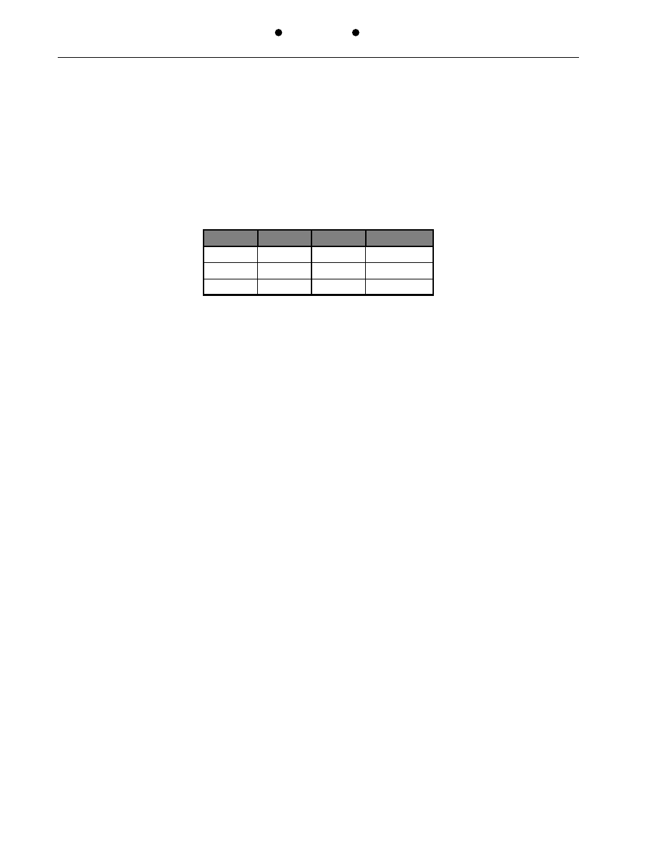
DTR / DSR Forced Active (JP8 thru JP12)
DTR is tied to DSR on each of the Sub-Channel ports. If the device connected does not
supply a DTR but requires DSR (DTE) or does not supply DSR but requires DTR (DCE),
installing the forced DTR/DSR jumper (JP8-JP12) for the appropriate Sub-Channel will solve
this problem. The line is forced to +8V via an 820
W
resistor, providing isolation to any driver
that might be on the interface.
Channel
Jumper
Channel
Jumper
Master
JP8
3
JP11
1
JP9
4
JP12
2
JP10
FACTORY Test Jumpers (JP1, JP2 and JP3)
The three test jumpers JP1, 2 and 3, must be installed for the unit to properly function. These
jumpers are used in the manufacture and test of the product prior to shipment.
- PATTON 2707/I (24 pages)
- 1015 (7 pages)
- ONSITE SERIES 2603 (133 pages)
- 2500RC (23 pages)
- 1094A (17 pages)
- 2135 (9 pages)
- 2720 (23 pages)
- 3210 (2 pages)
- IpLink 2888 (2 pages)
- 1025S (9 pages)
- 1004ABRC (13 pages)
- SMARTNODE 5400 (8 pages)
- 2312M (16 pages)
- Model 3088/I (61 pages)
- 3087 (10 pages)
- Patton RAS 3120 (2 pages)
- 1140 (8 pages)
- 2707D (20 pages)
- T1/E1 CHANNELIZED GIGABIT ROUTER 2884 (51 pages)
- CopperLink Ethernet Extenders 2158A (28 pages)
- 1170M SERIES (16 pages)
- CopperLink 07M2160-GS (107 pages)
- 1082/I (28 pages)
- 2884 (52 pages)
- 1002S (8 pages)
- 1058DVs (5 pages)
- S-DTA (30 pages)
- GoCard 1058 (2 pages)
- 1050patton (9 pages)
- 460 (5 pages)
- SMARTNODE 1400 (16 pages)
- G.SHDSL INTEGRATED 3086 (196 pages)
- 2620 (12 pages)
- 2020P (9 pages)
- 2192 (28 pages)
- 1053AS (2 pages)
- 1017 (5 pages)
- 1193 (11 pages)
- 504 (8 pages)
- SMARTNODE 4960 (68 pages)
- Industrial Ethernet Extender with LCD Interface 3231 (2 pages)
- Patton SmartNode 2300 Series (2 pages)
- 1092ARC (20 pages)
- Model 2711 (13 pages)
- 2701/D (28 pages)