Tea5880ts, Philips semiconductors – Philips TEA5880TS User Manual
Page 12
9397 750 13022
© Koninklijke Philips Electronics N.V. 2004. All rights reserved.
Preliminary data sheet
Rev. 02 — 26 April 2004
12 of 27
Philips Semiconductors
TEA5880TS
Integrated FM stereo radio IC for host processor tuning
[1]
The frequency is decreased when increasing the content of this register.
[1]
The frequency is increased when increasing the content of this register.
[1]
This register does not have an address. To read the status register, latch its content into the PISO (using
L_STS bit in control register B) then read out the PISO.
[1]
This register does not have an address. To read the counter register, latch its content into the PISO (using
L_CNT bit in control register B) then read out the PISO.
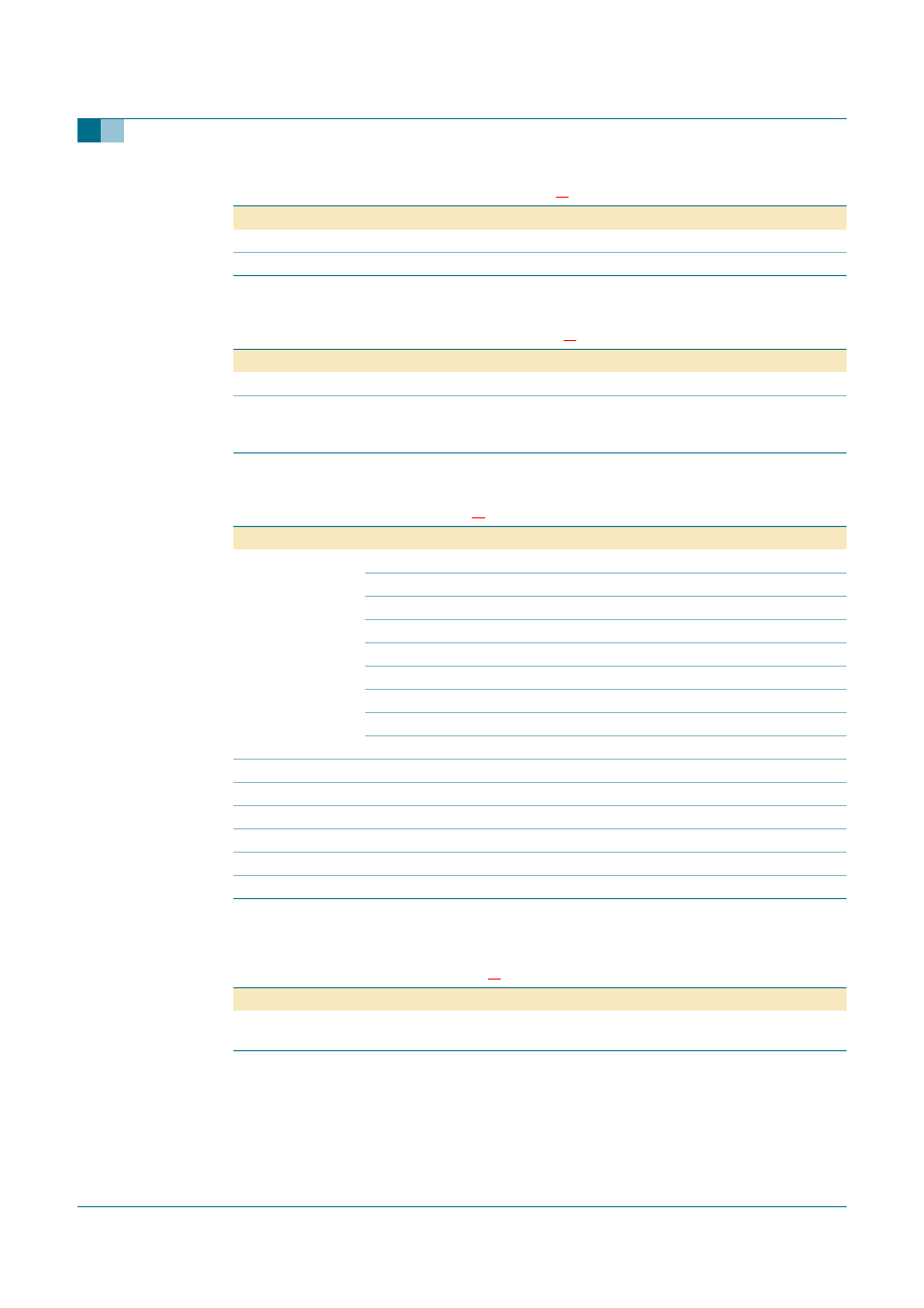
Table 15:
OSC_IF - (address 6h) bit description
Bit
Symbol
Description
14 to 11 -
address bits
10 to 0
IFO[10:0] 11-bit digital-to-analog converter for adjusting the IF frequency
Table 16:
OSC_FM - (address 7h) bit description
Bit
Symbol
Description
14 to 11 -
address bits
10 to 0
FO[10:0]
11-bit digital-to-analog converter for adjusting the FM frequency in fine steps;
this register is used in combination with the CAP_FM register to set a FM
frequency
Table 17:
STATUS - bit description
Bit
Symbol
Description
15 to 9
FS[6:0]
field strength, indicated by the amount of bits set:
0 bits set = < 10 dB
µ
V
1 bit set = 10 dB
µ
V to 20 dB
µ
V
2 bits set = 20 dB
µ
V to 30 dB
µ
V
3 bits set = 30 dB
µ
V to 40 dB
µ
V
4 bits set = 40 dB
µ
V to 50 dB
µ
V
5 bits set = 50 dB
µ
V to 60 dB
µ
V
6 bits set = 60 dB
µ
V to 70 dB
µ
V
7 bits set = > 70 dB
µ
V
8
-
not applicable; always read as logic 1
7 to 5
R[2:0]
chip revision; the revision for TEA5880TS is 100b
4 to 3
-
not applicable; always read as logic 1
2
-
reserved for production test
1
-
not applicable; always read as logic 1
0
-
reserved for production test
Table 18:
COUNTER - bit description
Bit
Symbol
Description
15 to 0
CNT[15:0]
pulses counted during the period that the counter is enabled and the NR/W
line the 3 wire bus is low