Fig 2, Fig 3 – Philips UPM51 User Manual
Page 4
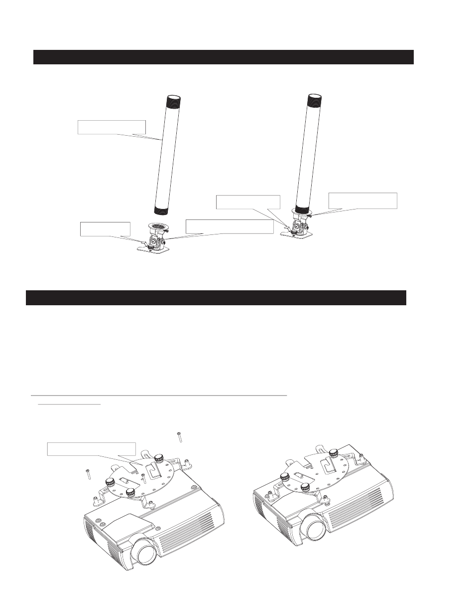
1. FASTEN THE PROJECTOR MOUNT TO 1 ½”NPT PIPE
1: The bracket must be secured to a ceiling structure capable of at least
2: Screw the bayonet sub assembly onto the 1 ½” NPT (not supplied).
3: Secure with the locking set screw making sure the sub assembly safety lever is facing the front of the projector.
SEE FIG 2
(4) times the weight of the projector + mount.
Fig 2
2. ATTACH THE ADAPTER PLATE TO THE PROJECTOR.
safety lever
locking set screw
Pipe Not Supplied
Bayonet Sub Assembly
Projector Front
Fig 3
Projector assembly
Adapter Plate Assembly
1: Start by screwing the leveling barrels ( A ) into the Adjustable arms (K and L). A screwdriver slot is provided in the barrel (A). The barrels only
need to be threaded approx. 1/8“ through the bottom of the arm (K and L). If the mounting plane of the projector is not flat, the barrels can be
adjusted to make up the difference in height.
2: Using the adapter plate ( M ) attach the adjustable arms ( K,L ) with the hardware supplied (B,C,F). No need to tighten at this time.
3: Place the Universal adapter plate onto the projector. Using the proper hardware supplied ( screws G,H,I,or J) (washers D or E )
lightly fasten to the projector.
SEE FIG 3
4: Position the universal adapter plate approx over the center of the projector. Tighten the screws to the projector and then tighten the plastic knobs
(You can also adjust the adapter plate assembly to access the filters and light source to suite.)
Be careful to not over tighten the projector screws.
Damage to the projector may occur if the screws to the projector are over tightened.
SEE FIG 3 for details
4