Powermate P1204 User Manual
Page 19
19
200-2667
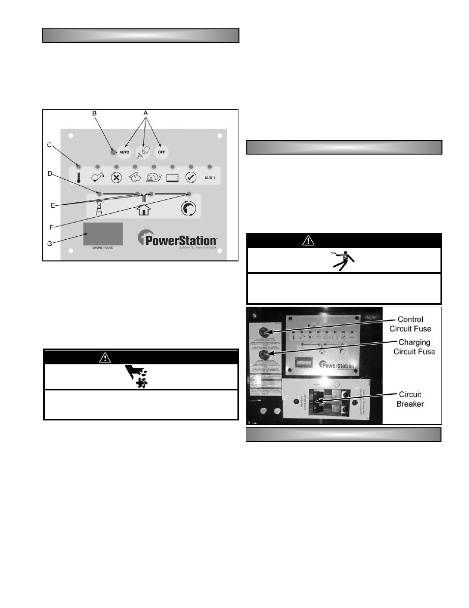
A. MODE BUTTONS (AUTO, MANUAL AND OFF)
B. AUTO LED
C. STATUS INDICATOR LED’s
D. UTILITY POWER MONITOR LED
E. TRANSFER SWITCH MONITOR LED
F. GENERATOR POWER MONITOR LED
G. HOUR METER
A. Mode
Buttons
The Mode Buttons are used to set the operating
state of the generator. Pressing the OFF button prevents
engine operation or stops the engine if it is already
running. Pressing the MANUAL button (center button)
immediately starts the generator. Pressing the AUTO
button sets the generator for unattended operation under
the control of properly matched automatic transfer
switch.
B. Auto
LED
The Auto LED will be green when the controller is
placed in the Auto Mode.
C. Status Indicator LED’s
Status Indicator LED’s are provided to communicate
the status of the generator to the user. Under normal
running conditions, only the green Auto LED is lit.
Function of all other LED’s are described on page 21.
D. Utility Power Monitor LED
The Utility Power Monitor LED will illuminate green
when the Voltage Sensing detects that the Utility is
available.
E. Transfer Switch Monitor LED
The Transfer Switch Monitor LED will illuminate
Green when the transfer switch is in the normal position
and it will illuminate Red when the Transfer Switch is in
the Emergency position.
F. Generator Power Monitor LED
The generator power monitor LED will illuminate Red
when the Voltage Sensing detects that the Generator
source is available.
G. Generator Hour Meter
The Generator Hour Meter is provided to track the
total numbers of hours of operation. The hour meter
runs whenever the engine is running and the alternator is
producing electricity. Placing the main line circuit
breaker in the OFF position while the engine is running
does not stop the meter from counting hours.
Main Line Circuit Breaker
A Main Line Circuit Breaker is provided to protect the
generator from damage caused by electrical faults within
the attached electrical distribution system. It is also used
to isolate the output of the generator from the connected
electrical distribution system by moving the breaker
handle to the OFF position. Placing the breaker in this
position does not prevent startup of the generator.
Control Circuit Fuse
The Control Circuit Fuse provides protection against
damage from electrical faults. Replace the fuse only with
an equivalent size and style of fuse to prevent damage to
the control system.
Charging Circuit Fuse
The Charging Circuit Fuse provides protection to the
engine mounted alternator in the event of electrical faults
in the positive (+) battery circuit. Failure of this fuse
prevents charge from reaching the battery when the
generator is running, leading to early battery failure.
Replace the fuse only with an equivalent size and style of
fuse to prevent damage to the control system.
C
C
C
C
O
O
O
O
N
N
N
N
T
T
T
T
R
R
R
R
O
O
O
O
L
L
L
L
P
P
P
P
A
A
A
A
N
N
N
N
E
E
E
E
L
L
L
L
F
F
F
F
E
E
E
E
A
A
A
A
T
T
T
T
U
U
U
U
R
R
R
R
E
E
E
E
S
S
S
S
W
WA
AR
RN
NIIN
NG
G
•
With the Mode in the auto position, the unit
starts and stops without notice.
•
Keep clear of all moving parts at all times.
W
WA
AR
RN
NIIN
NG
G
•
Place the circuit breaker in the OFF position
when servicing the generator to minimize
electrocution hazards.
C
C
C
C
II
II
R
R
R
R
C
C
C
C
U
U
U
U
II
II
T
T
T
T
B
B
B
B
R
R
R
R
E
E
E
E
A
A
A
A
K
K
K
K
E
E
E
E
R
R
R
R
F
F
F
F
U
U
U
U
S
S
S
S
E
E
E
E
S
S
S
S