Powermate P1204 User Manual
Page 17
17
200-2667
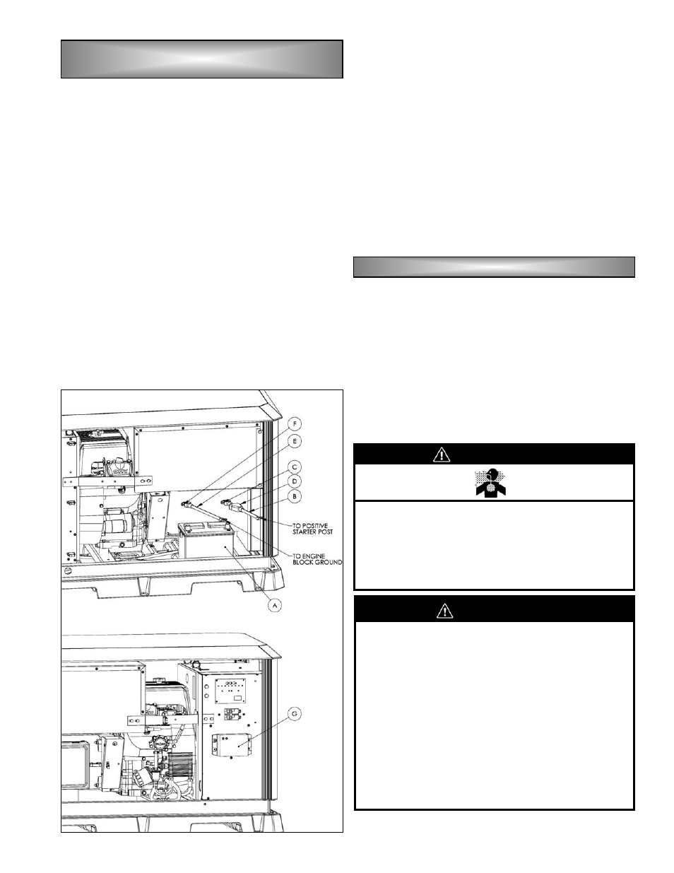
To access the battery and charger, remove the front
and back panels by inserting the key into the locks
located on top of the panel. and turn 1/4 turn
counterclockwise to unlock. Lift the panels up and out of
the base and set it aside.
Place the battery (A) on the base as shown in Fig G.
After the battery is set, begin attaching the battery
cables to the battery posts, starting with the positive (+),
or red, cable (B). Loosen the bolt (C) on the post clamp
slightly to allow the clamp to expand, then firmly push the
clamp onto the battery post marked positive (+) until the
top of the post extends past the top of the clamp. Rotate
the clamp around the post as required to insure the
clamp cannot contact any metal components, then
tighten the clamp bolt (C) until snug. Finally,slide the
post boot (D) down the cable and place it entirely over
the clamp.
Finish connecting the battery by placing the negative
(-), or black, battery cable (E) to the battery post marked
negative (-). Push the clamp firmly over the post until the
post extends past the top of the clamp, then rotate the
clamp to avoid contact with any metal parts. Tighten the
battery clamp bolt (F) until snug.
The final step of battery installation is to verify proper
connection of all battery charger connections. A battery
charging system (G) is included with the
engine/generator set to maintain the battery charge
during extended periods of generator inactivity, therefore
providing consistent starting. A quick check of charger
connections will verify that factory connections are
correct so the charger can function as intended. Insure
that the charger is connected by checking to see that it is
plugged into a powered receptacle, and that the positive
(+) and negative (-) charger cables are connected to their
respective battery cables.
Install the panels back onto the generator by placing
the bottom of the panel onto the base and pushing it up
into place. Lock the panel by inserting the key into the
locks and turning 1/4 turn clockwise.
Once all connections are made, the final installation
step is verification of proper engine oil level. Check oil
level before start-up (see page 23 for instructions). The
unit is shipped with the proper type of oil in the
crankcase for operation above 40°F. Follow the engine
manufacturer’s recommendations for oil at temperatures
below 40°F. Check oil periodically to ensure that the unit
is properly lubricated. Follow the engine manufacturer’s
recommended service schedule.
Engine oil capacity is 1.2 qt (1.14L) without a filter
change and 1.5qt (1.42L) with a filter change.
B
B
B
B
A
A
A
A
T
T
T
T
T
T
T
T
E
E
E
E
R
R
R
R
Y
Y
Y
Y
P
P
P
P
L
L
L
L
A
A
A
A
C
C
C
C
E
E
E
E
M
M
M
M
E
E
E
E
N
N
N
N
T
T
T
T
A
A
A
A
N
N
N
N
D
D
D
D
C
C
C
C
O
O
O
O
N
N
N
N
N
N
N
N
E
E
E
E
C
C
C
C
T
T
T
T
II
II
O
O
O
O
N
N
N
N
((
((
c
c
c
c
o
o
o
o
n
n
n
n
tt
tt
..
..
))
))
L
L
L
L
U
U
U
U
B
B
B
B
R
R
R
R
II
II
C
C
C
C
A
A
A
A
T
T
T
T
II
II
O
O
O
O
N
N
N
N
FIG. G
W
WA
AR
RN
NIIN
NG
G
•
State and federal agencies have determined
that contact with used engine oil can cause
cancer or reproductive toxicity. Take care to
limit skin contact and breathing of vapors as
much as possible. Use rubber gloves and wash
exposed skin.
C
CA
AU
UT
TIIO
ON
N
•
Too much oil can cause high oil consumption,
high operating temperatures and oil foaming.
Too little oil can cause severe engine damage.
Keep the oil level between the full and add
marks on the dipstick.
•
Any attempt to crank or start the engine before
it has been properly serviced with the
recommended oil will result in an engine failure
that is not covered under warranty.
•
Never run this equipment without the complete
air cleaner system installed on the engine.
Failure to do so will result in premature engine
wear and significantly reduced engine life.