Accessories – Lincoln Electric IDEALARC SVM 122-A User Manual
Page 36
CONNECTING THE LN-742 TO THE
IDEALARC DC-400 (14-PIN AMPHENOL)
1.
Disconnect main AC input power to the Idealarc
DC-400.
2.
Set the POWER toggle switch to the OFF (0) posi-
tion.
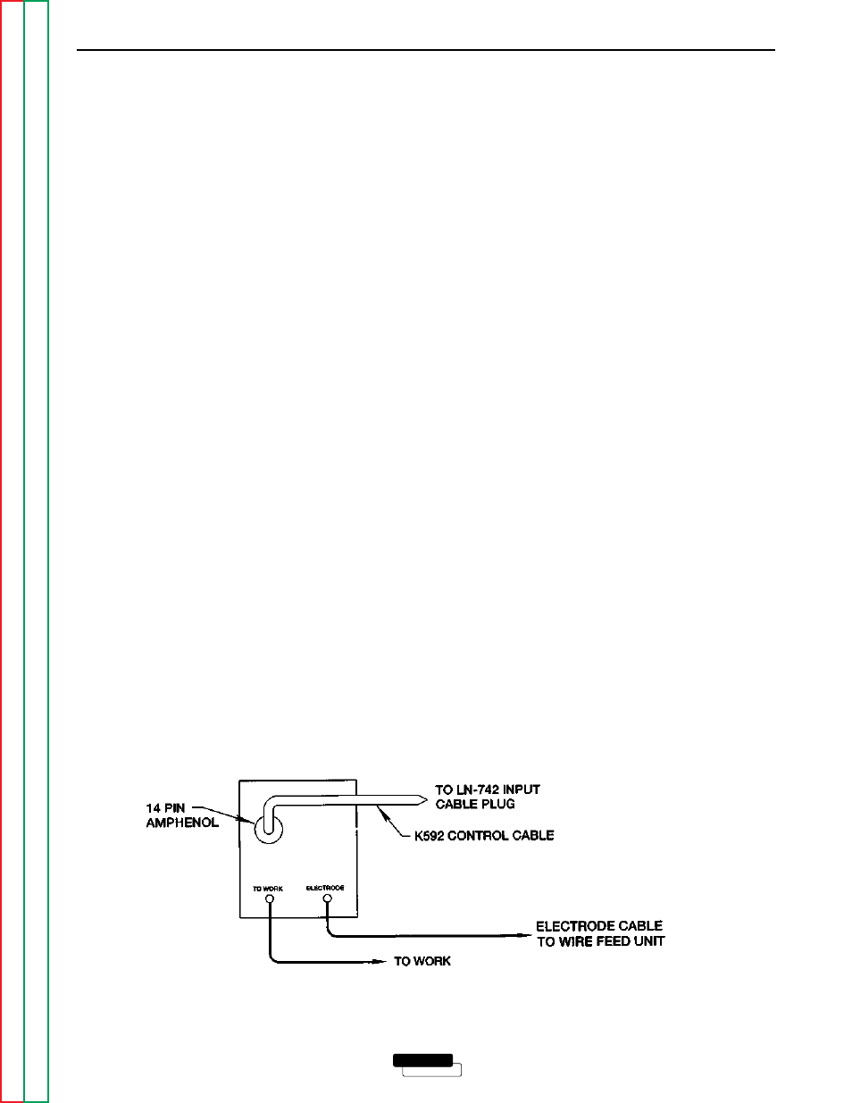
3.
Connect the electrode cable from the LN-742 to
the “+” terminal of the welder. Connect the work
cable to the “-” terminal of the welder. Reverse
this hookup for negative polarity. See Figure C.11.
NOTE: Welding cable must be sized for the current
and duty cycle of the application.
4.
Connect the K592 Control Cable to the 14-pin
amphenol on the IDEALARC DC-400 and to the
input cable plug on the LN-742. See Figure C.11.
5.
Set the welder VOLTMETER switch to the desired
polarity, either DC (-) or DC (+).
6.
Set the MODE switch to a CV (constant voltage)
position.
7.
Adjust wire feed speed at the LN-742 and set the
welding voltage with the output ARC CONTROL to
a CV (constant voltage) position at the welder.
NOTE: If optional remote control is used, set the
OUTPUT CONTROL switch to the “Remote”
position and the OUTPUT TERMINALS switch
to the “Remote” position.
ACCESSORIES
C-13
C-13
LINCOLN
®
ELECTRIC
IDEALARC DC-400
FIGURE C.11 – IDEALARC DC-400/LN-742 CONNECTION DIAGRAM