Accessories – Lincoln Electric IDEALARC SVM 122-A User Manual
Page 31
5.
Extend wire feeder control cable lead #21 so it can
be connected directly to the work piece.
a.
Make a bolted connection using AWG #14 or
larger insulated wire. Tape the bolted connec-
tion with insulating tape.
b.
An S-16586- X remote voltage sensing work
lead is available for this purpose.
c.
Keep the #21 lead electrically separate from
the work cable circuit and connection.
d.
Tape the #21 lead to work cable for ease of
use.
6.
Connect NA-5 wire feeder control jumpers on
Voltage Control Board. See NA-5 Operator’s
Manual.
NOTE: The connection diagram shown in Figure C.5
shows the electrode connected for positive
polarity. To change polarity:
a.
Set the Idealarc DC-400 POWER toggle
switch to the OFF (0) position.
b.
Move the electrode cable to the negative (-)
output terminal.
c.
Move the work cable to the positive (+) output
terminal.
d.
Set the VOLTMETER toggle switch to negative
(-).
NOTE: For proper NA-5 operation, the electrode
cables must be secured under the clamp bar
on the left side of the NA-5 Control Box.
7.
Set the DC-400 OUTPUT CONTROL switch to the
“Remote” position and the OUTPUT TERMINALS
switch to the “Remote” position.
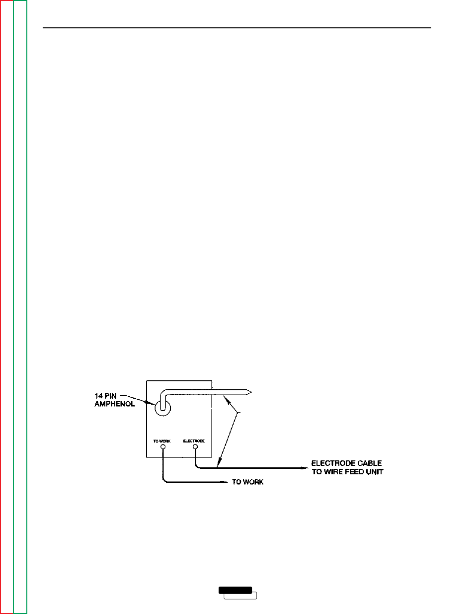
CONNECTING THE NA-3 OR NA-5 TO THE
IDEALARC DC-400 (14-PIN AMPHENOL)
1. Disconnect main AC input power to the Idealarc
DC-400.
2. Set the Idealarc DC-400 POWER switch to the OFF
(0) position.
3. Connect the electrode cable from the K597-XX
Input Cable Assembly to the “+” terminal of the
welder and to the wire feeder. Connect the work
cable to the “-” terminal of the welder. Reverse this
hookup for negative polarity. See Figure C.6.
NOTE: Welding cable must be sized for the cur-
rent and duty cycle of the application.
4. Set the welder VOLTMETER switch to the desired
polarity, either DC (-) or DC (+).
5. Set the MODE switch to a CV (constant voltage)
position.
6.
Set the DC-400 OUTPUT CONTROL switch to the
“Remote” position and the OUTPUT TERMINALS
switch to the “Remote” position.
ACCESSORIES
C-8
C-8
LINCOLN
®
ELECTRIC
IDEALARC DC-400
FIGURE C.6
IDEALARC DC-400/NA-3/NA-5 14-PIN AMPHENOL CONNECTION
TO NA-3 or NA-5 INPUT
CABLE PLUG
K597-XX INPUT CABLE ASSEMBLY