Accessories – Lincoln Electric IDEALARC SVM 122-A User Manual
Page 33
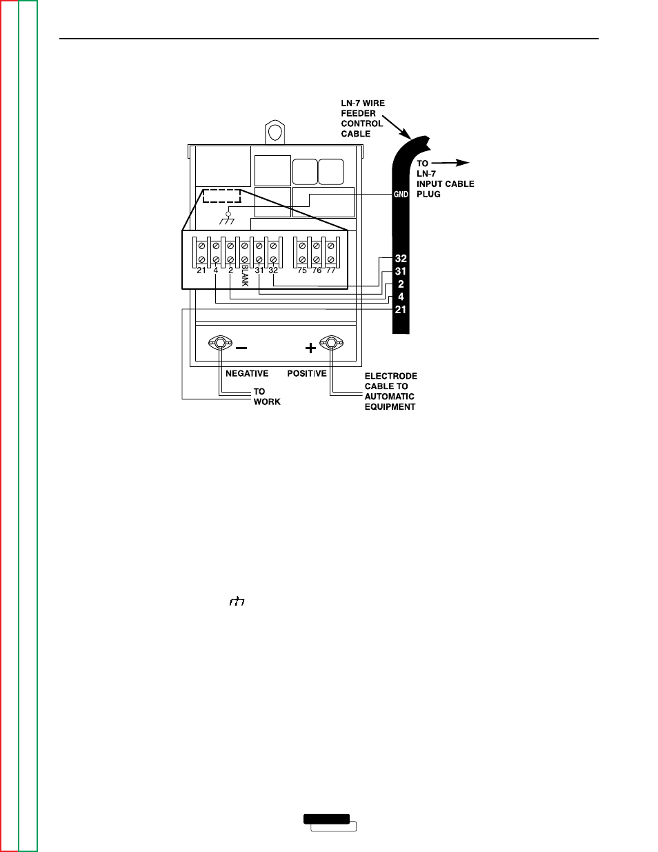
CONNECTING THE LN-7 TO THE
IDEALARC DC-400 (TERMINAL STRIP)
1.
Disconnect main AC input power to the Idealarc
DC-400.
2.
Set the Idealarc DC-400 POWER toggle switch to
the OFF (0) position.
3.
Connect the wire feeder control cable leads to the
Idealarc DC-400 terminal strip as shown in Figure
C.8.
4.
Connect the wire feeder control cable ground lead
to the frame terminal marked .
NOTE: The Idealarc DC-400 must be properly
grounded.
5.
PERFORM THIS STEP ONLY IF THE LN-7 IS
EQUIPPED WITH A METER KIT.
Extend wire feeder control cable lead #21 so it can
be connected directly to the work piece.
a. Make a bolted connection using AWG #14 or
larger insulated wire. Tape the bolted connec-
tion with insulating tape.
NOTE: If the work cable length is less than 25 feet
and the connections to the work piece are
secure, then wire feeder control cable lead
#21 can be connected directly to the DC-
400 terminal strip.
b. An S-16586- X remote voltage sensing work
lead is available for this purpose.
c. Keep the #21 lead electrically separate from
the work cable circuit and connection.
d. Tape the #21 lead to work cable for ease of
use.
NOTE: The connection diagram shown in Figure
C.8 shows the electrode connected for
positive polarity. To change polarity:
a. Set the IDEALARC DC-400 POWER toggle
switch to the OFF (0) position.
b. Move the electrode cable to the negative (-)
output terminal.
c. Move the work cable to the positive (+) output
terminal.
d. Set the VOLTMETER toggle switch to nega-
tive (-).
ACCESSORIES
C-10
C-10
LINCOLN
®
ELECTRIC
IDEALARC DC-400
FIGURE C.8 - LN-7 WIRE FEEDER CONNECTION TO THE IDEALARC DC-400