Life Fitness G4 User Manual
Page 18
S
TEP
15:
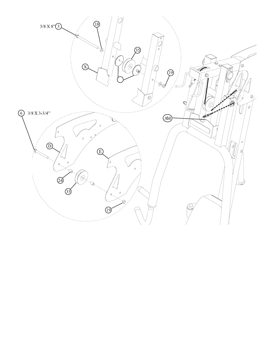
• Route the LAT CABLE (AM) through the PRESS ARM SUPPORT FRAME (X) and assemble one
3-1/2” PULLEY (35) to the FRAME PRESS ARM SUPPORT FRAME (X) using one 3/8 X 8” BOLT
(3), two 3/8” WASHERS (18), two PULLEY GUARD SPACERS (39) and one 3/8” SILVER LOCK
NUT (19). See FIGURE 15.
• Route the LAT CABLE (AM) around one 3-1/2” PULLEY (35) and assemble the PULLEY to the
LEFT (D) and RIGHT (E) BOOM PLATES using one 3/8 X 3-3/4” BOLT (6), two 3/8 X 1” SPAC-
ERS (24) and one 3/8” SILVER LOCK NUT (19). See FIGURE 15.
NOTE: Make sure the cable runs in the grooves of the pulleys.
17
39
F
IGURE
15
See also other documents in the category Life Fitness Sports and recreation:
- T3 Treadmill (6 pages)
- F3 Folding Treadmill (12 pages)
- T7 Treadmill (8 pages)
- T3 Treadmill (19 pages)
- T5 Treadmill (1 page)
- Platinum Club Series Treadmill (21 pages)
- Arctic Silver T3.5 Treadmill (9 pages)
- FZTP (17 pages)
- MTSLE (18 pages)
- Sport and Essential Consumer Treadmills (3 pages)
- CTSX30-0102-01 (8 pages)
- Cable Motion 8352100 REV. B (26 pages)
- Cable Motion 39721 (24 pages)
- Pro 2 Series PSPD (11 pages)
- 91Xi (83 pages)
- 91TW (22 pages)
- Utility Bench (8 pages)
- Hammer Strength OHDRacks (6 pages)
- 8216 (7 pages)
- GS5 (11 pages)
- TR-7500 (3 pages)
- Parabody 805 (11 pages)
- HDCR9 (13 pages)
- 18 \ 90 Series (8 pages)
- OHD-MIP (10 pages)
- Pro 2 Series PSFLY (10 pages)
- Hammer Strength OHDMR (15 pages)
- GS6 (1 page)
- UPRIGHT LIFECYCLE 95C (1 page)
- LIFECYCLE R3 (2 pages)
- GS4 (12 pages)
- FZHAD (13 pages)
- FIT 3 (1 page)
- 889 (16 pages)
- MTSRL (21 pages)
- 887 (16 pages)
- GK53-00002-0012 (2 pages)
- C3 (2 pages)
- Pro 2 Series PSSLPSE (22 pages)
- T7i (8 pages)
- Arctic Silver 93XW-0XXX-03 (17 pages)
- 874 (12 pages)
- Classic Series Cross-Trainer CLSXH (8 pages)
- Exercise Bike Inspire Console 97C Lifecycle (42 pages)
- Hammer Strength MTS (6 pages)