Xpress dr+ front panel, Figure 3-1. typical configuration – Lantronix XPress DR+ User Manual
Page 19
Chapter 3: Installation and Hardware
XPress DR+ User Guide
19
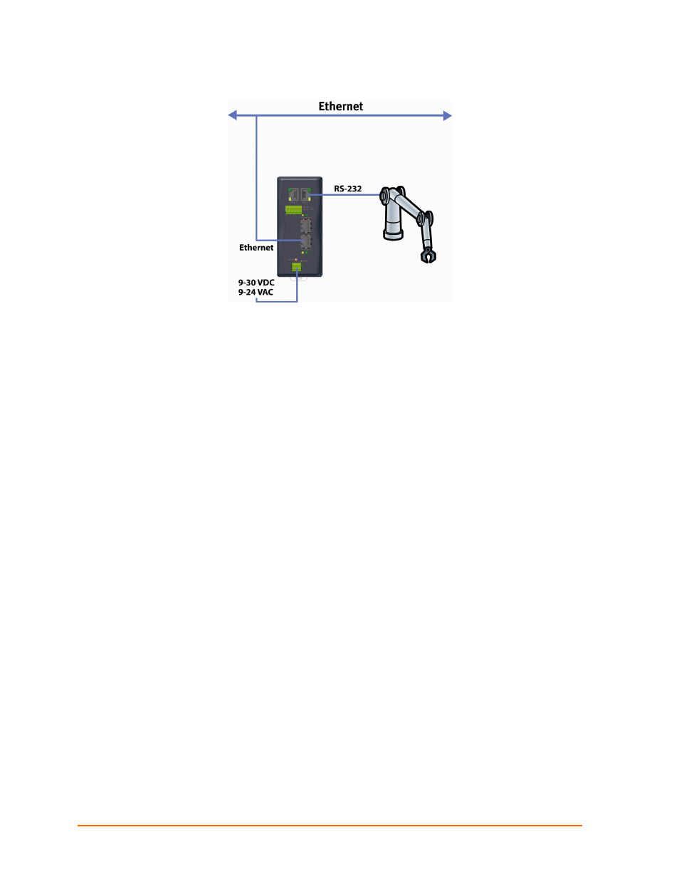
Figure 3-1. Typical Configuration
1. Connect a serial device to your XPress DR+. (See Serial Interface on page 20 for
cable and connector specifications.)
2. Connect an Ethernet cable to the Ethernet port. (See
3. Supply power to your XPress DR+ using a 9-30 VDC or 9-24 VAC (2.3W maximum)
source. (See
4. Supply power to the serial device.
Note:
Connecting a device to an active Ethernet network can disrupt
communications on the network. Make sure the device is configured for your
application before connecting it to an active network
XPress DR+ Front Panel
The following figure illustrates the screw block connector pinouts and other components
of the XPress DR+.
Note:
For a description of the XPress DR+W front panel, see