Land Pride Rear Blades RBT4096 User Manual
Page 16
14
Section 3: Set-Up of Accessories
RBT4084, RBT4096 & RBT40108 Rear Blades 301-206M
6/12/13
Section 3: Set-Up of Accessories
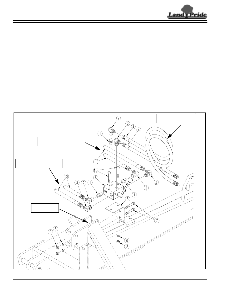
Hydraulic Selector Valve
Kit Bundle
301-188A . . . . . . . . . HYDRAULIC SELECTOR VALVE
Allows operation of 3 cylinders using 2 duplex outlets.
Refer to Figure 3-1:
1.
Using selector mount (#5) as a template, locate and
drill two 7/16" diameter holes on the back side of
hitch plate as shown.
2.
Attach selector mount (#5), to the back side of the
hitch with two 3/8"-16 x 1" GR5 hex head cap
screws (#7), spring lock washers (#8), and hex
nuts (#9). Tighten nuts to the correct torque.
3.
Attach double selector valve (#6) to selector
mount (#5) with two 3/8"-16 x 3" GR5 hex head cap
screws (#10), spring lock washers (#8), and hex
nuts (#9). Tighten nuts to the correct torque.
4.
Apply teflon tape to the pipe threads of three
3/4 x 1/2MNPT elbows (#3) and screw them into the
double selector valve as shown. Tighten to the
correct orientation.
5.
Apply teflon tape to the threads of the three
3/4JIC x 1/2MNPT adapters (#1) and screw them
into the double selector valve as shown until tight.
6.
Attach three 3/4JIC x 3/4JIC elbows (#2) to the
adaptors (#1). Tighten to the correct orientation.
7.
Attach frame offset hydraulic hoses (#11) to the
elbows on the back side of the selector valve.
8.
Attach hydraulic hoses (#12) from one of the other
cylinders to the elbows on the front side of the
selector valve.
9.
Attach tractor connected hydraulic hoses (#4) to the
top elbows.
10. Thread hydraulic couplings (couplings supplied by
customer) onto hydraulic hoses (#4) and tighten.
Hydraulic Selector Valve Assembly
Figure 3-1
17684
RILL (2) - 7/16"
DIA. HOLES
Hydraulic Hoses Leading From
the Frame Offset Cylinder
Hydraulic Hoses that Attached
to the Tractor Duplex Outlets
Hydraulic Hoses Leading From
One of the Other Cylinders