Rbt40 rear blade, Danger, Table of contents rbt40 rear blade – Land Pride Rear Blades RBT4096 User Manual
Page 10
8
Section 1: Assembly & Set-Up
RBT4084, RBT4096 & RBT40108 Rear Blades 301-206M
6/12/13
RBT40 Rear Blade
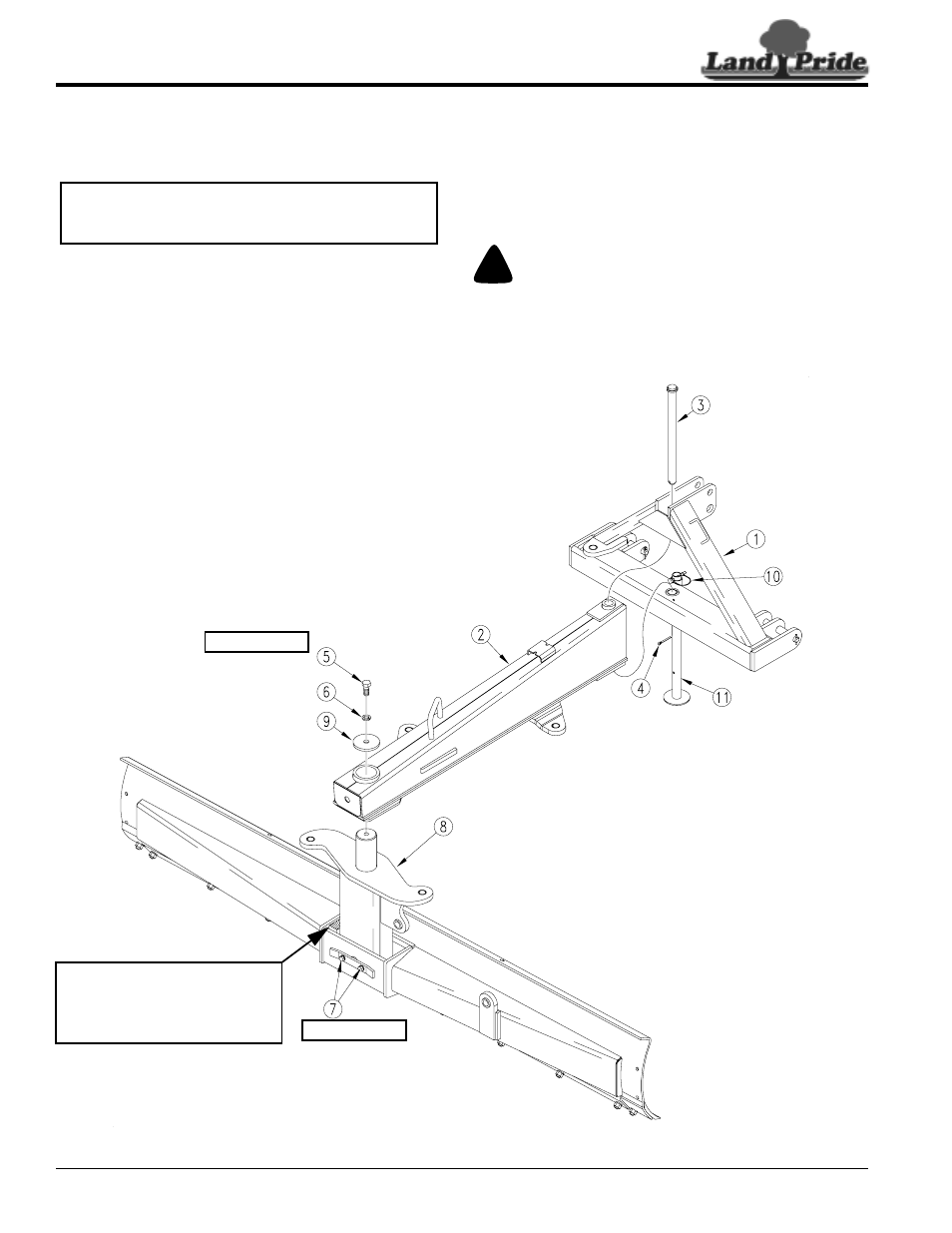
1.
On a level surface, remove and separate 3-Way Rear
Blade components from the shipping crate.
Refer to Figure 1-1:
2.
With a lifting device, set blade pivot assembly (#8)
upright.
3.
Remove pivot bolt (#5), lock washer (#6), and pivot
cap (#9) from blade pivot shaft (#8).
4.
Rotate moldboard 90˚ to the main frame and insert
blade pivot shaft (#8) into main frame (#2).
5.
Reinstall pivot cap (#9), lock washer (#6), and
3/4"-16 x 1 3/4" GR5 hex head cap screw (#5).
Tighten cap screw to the correct torque.
6.
Remove wire pin (#10) and slide support stand (#11)
all the way down. Reinstall wire pin.
7.
Lower unit to ground and unhook from lifting device.
8.
Remove cotter pin (#4) and pivot shaft (#3) from hitch
frame (#1).
9.
Attach hitch frame (#1) to a lifting device or to a
tractor.
IMPORTANT: Do not remove shipping block from
blade tilt housing until after ALL cylinders, manual
links, and/or ratchet jack have been installed.
10. Insert pivot shaft (#3) through top hole in hitch frame,
front hole in main frame (#2) and out through bottom
hole in hitch frame. Secure pivot shaft with 1/4" x 2"
cotter pin (#4).
11. Re-check all hardware for tightness. Torque all bolts
to specifications as listed in the “Torque Values
Chart” on page 28.
!
DANGER
Always check all hardware for tightness before using or
working around the blade. The moldboard will fall if blade
pivot bolt(s) securing pivot shaft to mainframe or blade tilt
bolt(s) securing tilt pin to moldboard carrier are loose or
missing.
Rear Blade Assembly
Figure 1-1
17681
SHIPPING BLOCK
DO NOT REMOVE UNTIL AFTER ALL
HYDRAULIC CYLINDERS AND/OR
RATCHET JACK AND MANUAL
LINKS HAVE BEEN INSTALLED.
Blade Pivot Bolt
Blade Tilt Bolts