Nstallation – Liebherr HC1050 User Manual
Page 13
A delight in freshness
HC 1001 / HC 1050
8
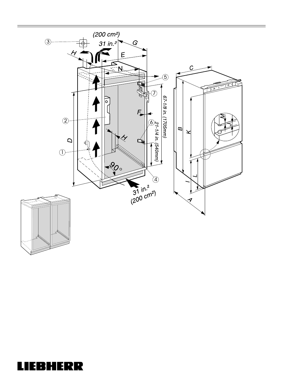
Figure 7
Make a separate kitchen cabinet for each appliance for Side by Side installations.
1
Fish line for power cord
2
Level
3
Electrical Outlet, The top of the electric outlet must be
located within 82-5/8 in. (2100 mm) (Figure 2) from the top
of the base in the cabinet.
4
Place shims under appliances as necessary
5
Upper cabinet spacer for 24 in. (610 mm) cabinet width
(dimension “E”) ONLY
6
Lower cabinet spacer for 24 in. (610 mm) cabinet width
(dimension “E”) ONLY
7
Kitchen Cabinet Hinge
A. 21-7/32" (544 mm)
B. 69-5/8" (1772 mm)
C. 21-1/4" (540 mm)
D. 69-25/32" - 70-3/8" (1772 - 1788 mm)
E. 24" (609.6 mm) (American Style Cabinet)
23-5/8" (600 mm) (European Style Cabinet)
G. 21-21/32" (550 mm) minimum
H. 1-1/2". (38 mm) minimum
I. 26-13/16" (681 mm)
J. 15/16" (24 mm)
K. 39-27/32" (1012 mm)
L. 26-1/8" (664 mm)
M. 1/8" (3 mm)
N. 21-7/16" (544.5 mm)
(clearance needed between kitchen cabinet hinge
projection and inside of left wall of kitchen cabinet)
Ventilation space at least 31 in.² (200 cm²) is required.
I
NSTALLATION
- FDv 4613 (19 pages)
- FDv 4613 (18 pages)
- FT 2902 (5 pages)
- FDv 4613 (36 pages)
- FDv 4613 (26 pages)
- FDv 4613 (51 pages)
- TP 1760 Premium (14 pages)
- GPesf 1476 Premium (12 pages)
- CBNPes 3756 Premium BioFresh NoFrost (18 pages)
- CP 3813 Comfort (14 pages)
- KBes 4260 Premium BioFresh (16 pages)
- KP 3620 Comfort (12 pages)
- KP 2620 Comfort (12 pages)
- TP 1414 Comfort (12 pages)
- TP 1410 Comfort (12 pages)
- IKB 2350 Premium BioFresh (12 pages)
- UIK 1424 Comfort (10 pages)
- CBNPgb 3956 Premium BioFresh NoFrost (20 pages)
- CBNPes 3967 PremiumPlus BioFresh NoFrost (26 pages)
- CNP 3513 Comfort NoFrost (16 pages)
- ICBN 3366 Premium BioFresh NoFrost (16 pages)
- ICN 3366 Premium NoFrost (12 pages)
- ICU 3314 Comfort (12 pages)
- GT 6122 Comfort (7 pages)
- CBNes 6256 PremiumPlus BioFresh NoFrost (13 pages)
- CUN 3523 Comfort NoFrost (14 pages)
- CUP 3021 Comfort (12 pages)
- WTes 5972 Vinidor (11 pages)
- WTpes 5972 Vinidor (13 pages)
- WTb 4212 Vinothek (9 pages)
- WKt 4552 GrandCru (11 pages)
- WKr 1811 Vinothek (9 pages)
- GTP 2356 Premium (7 pages)
- ICP 3314 Comfort (12 pages)
- IK 1950 Premium (10 pages)
- IK 3514 Comfort (10 pages)
- IK 2310 Comfort (10 pages)
- UIK 1550 Premium (14 pages)
- GN 3613 Comfort NoFrost (12 pages)
- WTes 1753 Vinidor (13 pages)
- WTr 4211 Vinothek (9 pages)
- WTEes 2053 Vinidor (12 pages)
- WTUes 1653 Vinidor (13 pages)
- WKt 6451 GrandCru (5 pages)
- WKt 4551 GrandCru (11 pages)