Sidewall direct venting – Lochinvar Shield SNR200-100 User Manual
Page 25
25
3
Sidewall direct venting
(continued)
All vent pipes and air inlets must terminate
at the same height to avoid possibility of
severe personal injury, death, or substantial
property damage.
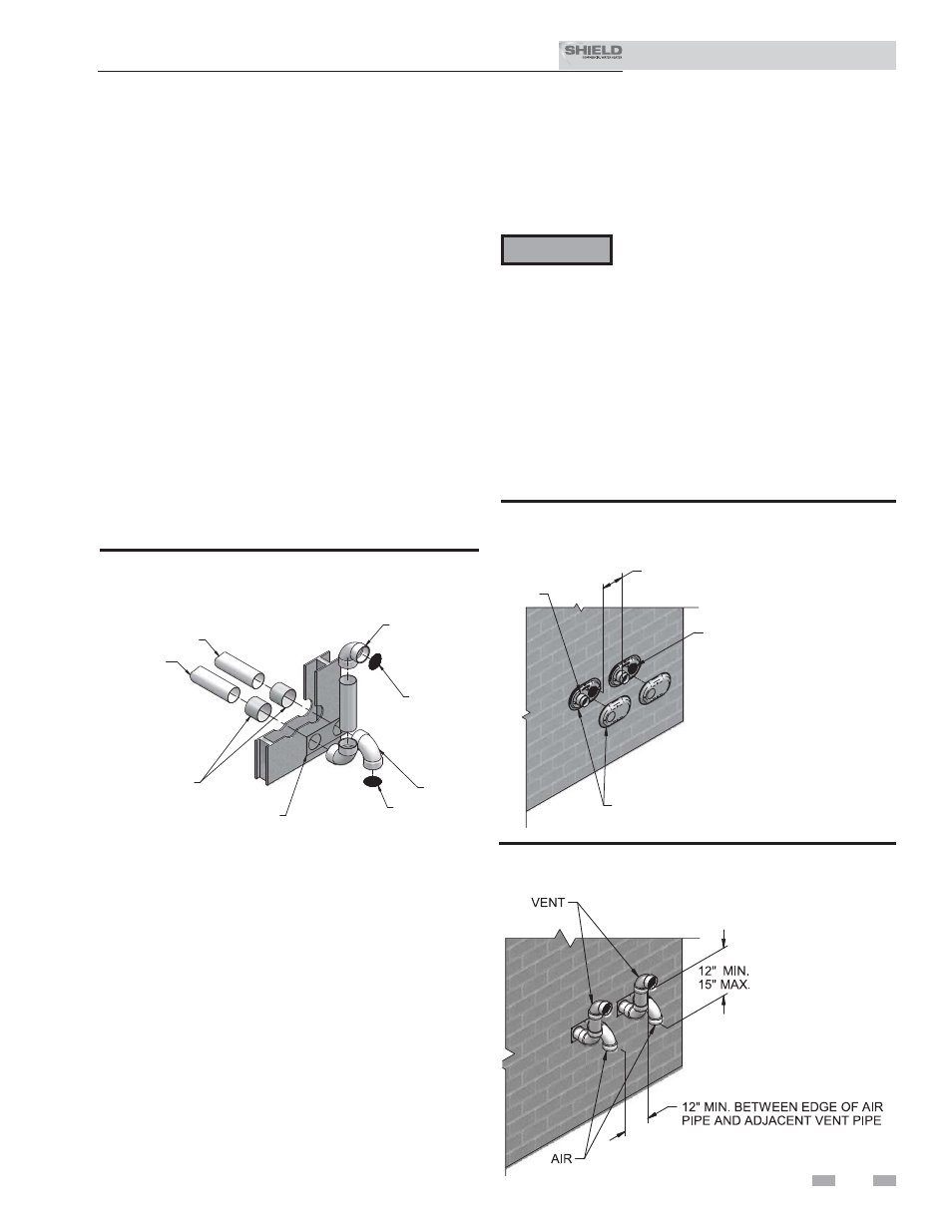
Multiple vent/air terminations
1. When terminating multiple Shield water heaters terminate
each vent/air connection as described in this manual
(FIG. 3-5A).
ƽ WARNING
2. Place wall penetrations to obtain minimum clearance of
12 inches between edge of air inlet and adjacent vent outlet,
as shown in FIG. 3-5A for U.S. installations. For Canadian
installations, provide clearances required by CSA B149.1
Installation Code.
3. The air inlet of a Shield water heater is part of a direct vent
connection. It is not classified as a forced air intake with
regard to spacing from adjacent water heater vents.
12" MIN. BETWEEN EDGE OF AIR
INLET AND ADJACENT VENT OUTLET
VENT / AIR
TERMINATION
VENT
AIR
Figure 3-5A Multiple Vent Terminations (must also
comply with Figure 3-1A)
Figure 3-5B Alternate Multiple Vent Terminations w/Field
Supplied Fittings (must also comply with Figure 3-1B)
Installation & Service Manual
TM
AIR PIPING
ELBOW
BIRD SCREEN
ELBOW
BIRD SCREEN
SIDEWALL
TERMINATION PLATE
GALVANIZED
THIMBLE
VENT PIPING
Figure 3-4B Alternate Sidewall Termination Assembly
w/Field Supplied Fittings
Prepare wall penetrations (Alternate -
Field Supplied Option)
1. Air pipe penetration:
a. Cut a hole for the air pipe. Size the air pipe hole as
close as desired to the air pipe outside diameter.
2. Vent pipe penetration:
a. Cut a hole for the vent pipe. For either combustible
or noncombustible construction, size the vent pipe
hole with at least a 1/2 inch clearance around the
vent pipe outer diameter:
• 4½ inch hole for 3 inch vent pipe
• 5½ inch hole for 4 inch vent pipe
b. Insert a galvanized metal thimble in the vent pipe
hole as shown in FIG. 3-4B.
3. Use a sidewall termination plate as a template for correct
location of hole centers.
4. Follow all local codes for isolation of vent pipe when
passing through floors or walls.
5. Seal exterior openings thoroughly with exterior caulk.
Termination and fittings
1.
The air termination coupling must be oriented at least
12 inches above grade or snow line as shown in FIG.
3-1A, page 22.
2. Maintain the required dimensions of the finished
termination piping as shown in FIG. 3-1A, page 22.
3. If using the alternate sidewall termination do not extend
exposed vent pipe outside of the building more than what
is shown in this document. Condensate could freeze and
block vent pipe.