Warning – Lennox Hearth MPD35ST-NM User Manual
Page 6
NOTE: DIAGRAMS & ILLUSTRATIONS NOT TO SCALE.
6
WARNING
Handle this glass with extreme
care! Tempered glass is suscep-
tible to damage – do not scratch
or handle roughly while rein-
stalling the glass door frame.
Inspect and clean all wire connections. Ensure
that there is no melting or damage. Inspection
should include:
• Terminals at the Valve
• OFF/ON Switch
• (Optional Control Switch) Wall Thermostat,
Remote Control or Remote Wall Switch Kit
Inspect Burner Flame Appearance
Ensure that the burner flame appearance
resembles the fl ame shown in Figure 13 and as
described in Flame Appearance and Sooting on
Page 9. The Homeowner must contact a quali-
fi ed service technician at once if any abnormal
condition is observed.
Small Area Paint Touch-up
The fi nish of the appliance is a high qual-
ity powdercoat. Only use factory supplied
powdercoat paint kit for touch-ups. Paint is
available at your local authorized Lennox Hearth
Products dealer (cat. no. 90L74). Never attempt
to paint a hot fi replace.
Do not attempt to repaint the appliance until the
fi nish is completely cured (see Burn-In Period
on Page 3 ). If the surface later becomes stained
or marred, it may be lightly sanded and touched
up with spray paint.
Front Glass Enclosure Panel, Removal
and Installation
WARNING
Do not operate appliance with the
glass front removed, cracked or
broken. Replacement of the glass
should be done by a licensed or
qualifi ed service technician.
WARNING
Do not attempt to substitute the
materials used on this door, or
replace cracked or broken glass
with any materials other than
those provided by the appliance
manufacturer.
WARNING
The glass door of this appli-
ance must only be replaced as a
complete unit as provided by the
manufacturer. Do not attempt to
replace broken, cracked or chipped
glass separately.
WARNING
Do not attempt to touch the front
enclosure glass with your hands
while the fi replace is in use.
These are direct-vent appliances. They are
designed to operate only when the front glass
enclosure panel is installed. Generally the front
glass enclosure panel should not be removed
except to gain access to the components within
the fi rebox, and the appliance may only be oper-
ated without the front glass enclosure panel
in place for very brief periods of time during
appliance checkout and adjustment. Note: The
fl ame appearance will be diminished while the
front glass enclosure panel is removed.
During this appliance checkout and adjust-
ment period, a potential safety hazard exists
- EXERCISE EXTREME CAUTION to prevent
the occurrence of any burn injuries from the
exposed fl ames or hot surfaces. Also note, that
while the front glass enclosure panel (or any of
the panels) is removed, the fl ame appearance
will appear to be smaller than normal.
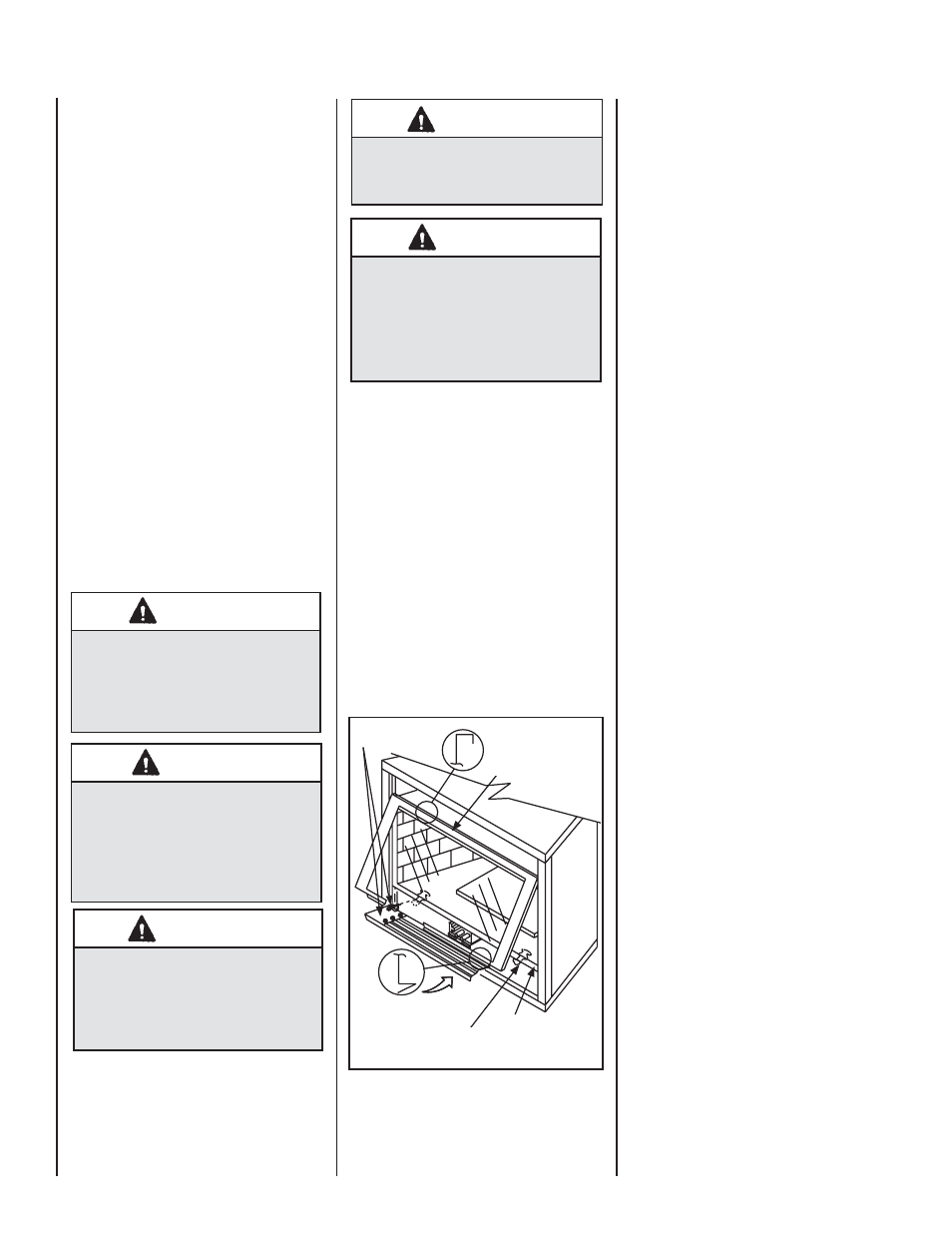
Figure 4
- INSTALLING GLASS DOOR
Lower Compartment
Door and Hinge
Top Flange on
Glass Door
Bottom Vee-fl ange
Glass Door
Glass Door Latch
Glass Door
Firebox Floor
Removing Glass Enclosure Panels
(see Figure 4)
1. Remove the top louver assembly or radiant
panel by pulling it out and off.
2. Open the control compartment access panel.
by actuating the spring-loaded magnetic
catches securing the panel (gently depress the
outer top corners of the louvered or radiant
panel until the catches "pop" the door free,
allowing it to swing out and down to the open
position).
3. Locate the two (2) latches at the top of the
control compartment. To disengage the two
latches from the bottom vee-fl ange of the
glass enclosure panel, reach for the handles
located towards the back of the latches and
pull the handles down toward the front of
the appliance.
4. Swing the bottom of the door out and raise
it slightly to lift the top fl ange of the door
frame away from the appliance.
Installing Glass Enclosure Panels
(see Figure 4 )
1. Visually inspect the gasket on the backside of
the panels. The gasket surface must be clean,
free of irregularities and seated fi rmly.
2. Position the glass enclosure panel in front of
the fi rebox opening at a 45 degree angle and
engage the top fl ange over the lip at the top
of the fi rebox opening. See Figure 4.
3. Swing the glass enclosure panel down and
back. Ensure the gasket seats evenly as the
panel draws shut. Engage the Vee-fl ange at
the bottom of the panel with the latches and
close the latches to secure the panel.
4. Close the bottom control compartment
access panel.