Diagrams, Idealarc® dc-1000 – Lincoln Electric IDEALARC IM420-D User Manual
Page 24
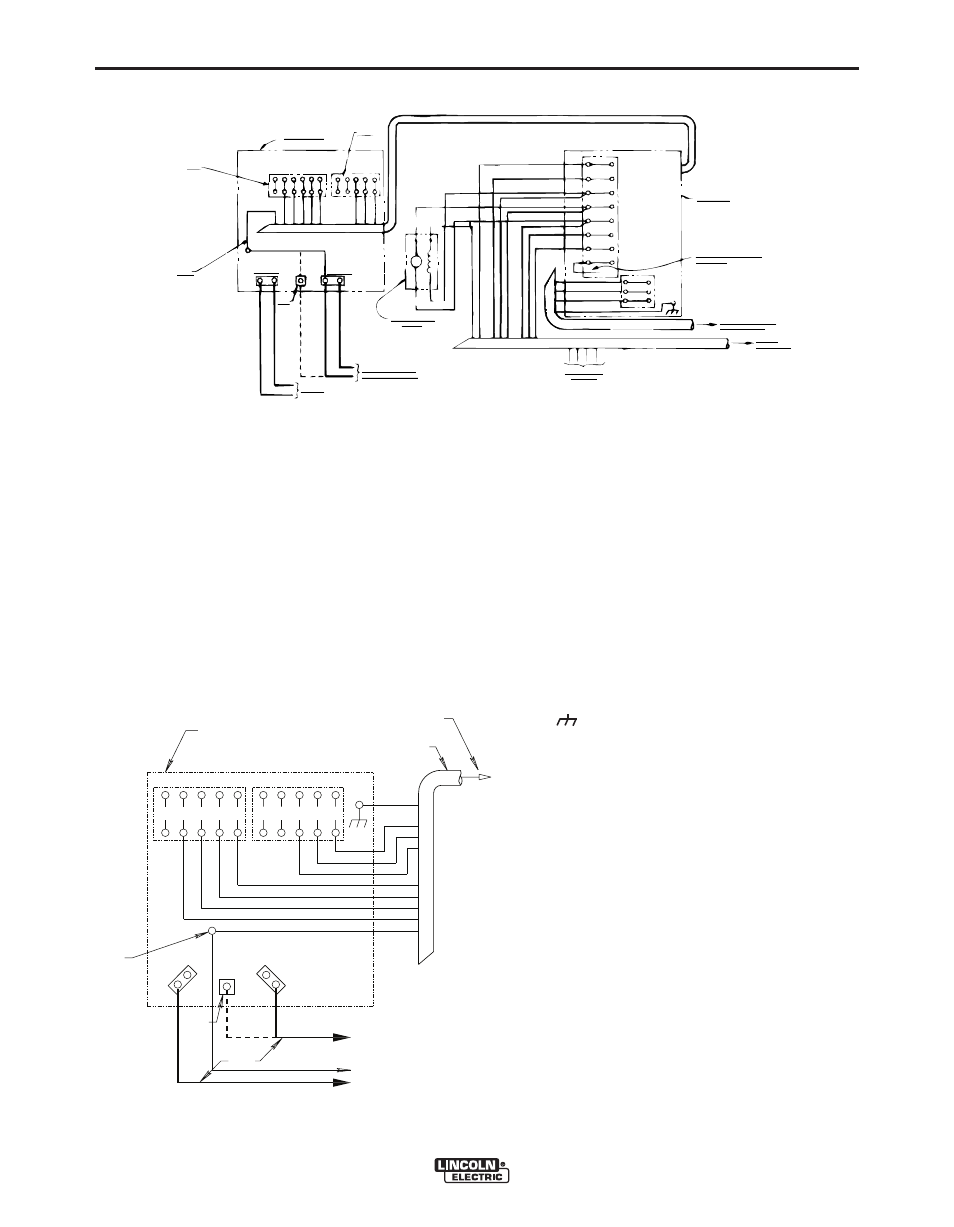
F-1
DIAGRAMS
F-1
IDEALARC® DC-1000
CONNECTION OF DC-1000 WITH NL OPTION KIT TO LAF-3 (Obsolete)
N.A.
On all DC-1000 and DC-1500 units
with codes above 8234 extend lead
67 and connect it to the electrode
cable going to the automatic equip-
ment.
N.B.
On DC-1500 units below code 8234
this is 67 and the LAF-3 #67 lead can
be connected either to the #67 termi-
nal or the electrode cable terminal as
shown. Terminal 82 not present on
later D.C. 1500’s and all DC-1000’s.
N.C. Terminals 73 and 74 not present on
earlier DC-1500’s.
N.D. Alternative 500 amp positive terminal
connection provided on DC-1000
models above code 9500 only.
This diagram shows the electrode connect-
ed positive. To change polarity, turn power
source off, reverse the electrode and work
leads at the power source and position the
switch on the power source and NL Option
Kit to the proper polarity. Also reverse the
leads on the back of the ammeter and volt-
meter in the LAF-3 control box.
Contactor drop out delay switch on the NL
Option Kit must be in the “On” position.
The 4/0 cables shown will handle up to
1000 amps at 80% duty cycle. For higher
currents or duty cycle add additional cables
to the power source output studs.
For best arc striking when connected to an
LAF-3 make the following change inside
the LAF-3 control unit. Remove the blue
jumper lead connected between #1 on the
coil of the main relay and #7 on the coil of
the transfer relay. (The main relay is the
upper right relay when facing the left end of
the control box. The transfer relay is just to
the left of the main relay.)
S17176
8-2-90F
CONNECTION OF DC-1000 TO LN-8
Connect the control cable ground lead to the frame terminal
marked near the power source terminal strip. The power
source must be properly grounded.
*If using an older control cable: Connect lead #75 to #75 on ter-
minal strip, connect lead #76 to #76 on terminal strip, connect
lead #77 to #77 on terminal strip.
N.A.
Welding cables must be of proper capacity for the current
and duty cycle of immediate and future applications.
N.B.
Extend lead 21 using #14 or larger insulated wire physi-
cally suitable for the installation. An S16586-[ ] remote
voltage sensing work lead is available for this purpose.
Connect it directly to the work piece keeping it electrically
separate from the welding work lead circuit and connec-
tion. For convenience, this extended #21 lead should be
taped to the welding work lead.
N.C. Tape up bolted connection.
N.D. Alternative 500 amp positive terminal connection provided
on DC-1000 models above code 9500 only.
Above diagram shows electrode connected positive. To change
polarity, turn power source off, reverse the electrode and work
leads at the power source and position the switch on power
source to proper polarity.
82
21
4
2
31 32
77
76
75
74
73
67
21
4
2
31
32
75
76
77
N.C.
POWER SOURCE
N.B.
N.A.
NEGATIVE
POSITIVE
N.D.
TO WORK
ELECTRODE CABLE TO
AUTOMATIC EQUIPMENT
35 VOLT CONTROL
EXCITER
21
1
6
4
2
1
10
21 32 31
18
45
29
5
TAPE UP LEADS
NOT USED
K775 REMOTE CONTROL
MOUNTED AT LAF-3
TO LAF-3
CONTROL BOX
CONNECT THE RED LEAD TO
TERMINAL 22
75
76
77
75
76
77
GND
22
31
32
21
10
1
2
4
NL OPTION
10
6
E
D
F
C
2 1 4
2
3 1 3 2
7 3 7 4 7 5 7 6 7 7
4
G
N
D
P O W E R S O U R C E
N E G A T I V E
P O S I T I V E
2 1
N . A .
E L E C T R O D E C A B L E T O
T O W O R K
}
T O L N - 8 I N P U T
C A B L E P L U G
C O N T R O L C A B L E
3 2
3 1
2
C
B
A
} *
W I R E F E E D U N I T
N . D .
N . B . &
N . C .
M13321
8-2-90F